
Finally I’ve made a huge step forward in actually controlling the Itho ventilation box from my arduino, using a CC1150 RF-transmitter. This wouldn’t have been possible without Sander letting me swap my Itho remote control for his remote control, so thanks Sander!
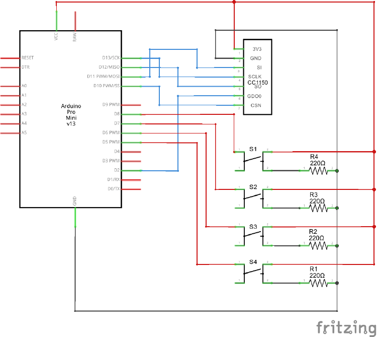
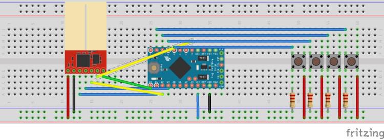
If you are not interested in how I got this working, but want to see it working for yourself, head straight on over to my GitHub repository and download the code: https://github.com/xs4free/Itho-library. Take a look at the AllFourButtons example. If you have a CC1150 RF transmitter, an Arduino Pro Mini (running at 3.3V) and 4 tactile switches, you can control an Itho RFT ventilation box by wiring up the compents like this:
In retrospect I had to solve 3 problems to get the code working:
- Know which fields contain the identity of the remote control (so I can re-create that number or create a fake number)
- Find out what the last 2 bytes in the first part of the message mean
- Find out what the 2 sets of bytes mean in the second part of the message that keep on changing every button press
The first problem (I thought) I had, was not knowing which bytes in the message actually contain the remotes unique identifier. My theory was that I had to generate another identifier for my Arduino based remote, or else the original remote would not work anymore. In the end it turns out both remotes work just fine when used interchangeable, but I didn’t know that up front. So I asked my colleague Sander if I could borrow his remote. That way I could analyze the messages being sent from his remote and analyze the differences. For each button press the Itho remote sents out 6 short RF messages. The first and second message are unique, the 4 messages after that are only repeats of the first 2. The first message contains 20 bytes in total, 6 bytes where different between the first and second remote. The second message contains 51 bytes in total, 5 bytes where different between the first and second remote. These were the only bytes that changed between the 2 remote controls, but stayed the same between 2 button presses on the same remote. I’m assuming the Itho ventilation box remembers these numbers when you preform the “join” operation when the ventilation box is turned on for the first time. Anyone using my code should perform a join first (untested yet!) with the identifiers in my code, before an Itho ventilation box will accept commands from the Arduino.
When I was analyzing the first message being sent for each button press, I noticed that the last 2 bytes only use a limited number of values. After looking at all the traces I had recorded I concluded that the last 2 bytes specify the previous command sent by the controller. So if the previous command was “go to low speed” and the command being sent now was “go to full speed”, the last two bytes of the first message would always be 85 and 77 (low speed). Each button/command has it’s own unique combination for these 2 bytes.
The second message that is being sent when a button is pressed, contains 51 bytes of data. This message contains 6 bytes that change every time you press a button (even if you keep pressing the same button over and over again). The only explanation I could think of, was that these bytes had to form a number that gets incremented with each button press. To find out what logic is being used to generate these numbers I put the 6 changing numbers in their own excelsheet and started searching for patterns and applying formulas. After a lot of searching I discovered that the 6 bytes formed 2 numbers, one that decrementes every button press and one that increments/decrementes based on the button that is being pressed and the previous button that was pressed before it. For example, if the Itho is running at low speed (was the last button pressed), and counter 1 currently has the value 100 and counter 2 has the value 200:
| Itho current speed | low | low | high | high | timer |
|---|---|---|---|---|---|
| Button pressed | high | high | timer | medium | |
| Message 1 last 2 bytes | 85, 77 | 85, 53 | 85, 53 | 85, 85 | |
| Message 2 counter 1 | 100 | 99 | 98 | 97 | 96 |
| Message 2 counter 2 | 200 | 203 (+3) | 204 (+1) | 210 (+6) | 206 (-4) |
The counters in message 2 are not simply stored in two bytes, but are split across the bits of 3 bytes. The assumption I made in my excelsheets, to convert the binary bits back to bytes, actually made it harder for me to see these number. For example, if bytes 26, 27 and 28 of the first message contain the values 150, 150 and 166, then the number we are looking for is 99. How did I calculate this number? First you convert the byte values to bits, so 150 becomes: 10010110 and 166 becomes: 10100110. If you put all 3 binary numbers after each other you get 10010110 10010110 10100110. Now take the 10th bit (from the left), the 8th bit, the 6th, 4th, 2nd, 18th, 16th, 14th and 12th. If you put these bits after each other, you get: 001100011. If you convert this binary number back to decimal, you get 99. The fun part for this counter is, that besides the number 99 the Itho remote always sends another number along with this counter. To calculate the value of the other number you substract the value of the counter (99) from 511, so the second number would be 511 - 99 = 412.
The second counter in message 2 uses the same kind of formula, only the first bit of the counter does not start at the 10th bit, but at the 14th bit.
So my current understanding of the protocol the Itho remote uses to communicate with the ventilationbox is as follows:
Message 1:
| Byte start | Byte end | Default value | Description |
|---|---|---|---|
| 1 | 3 | 170 | Start of the message (10101010 x 3) |
| 4 | 6 | 173,51,83 | header |
| 7 | 9 | id of the remote | |
| 10 | 10 | id (7 bits) + command (1 bit) | |
| 11 | 13 | The command | |
| 14 | 14 | command (7 bits) + checksum (1 bit) | |
| 15 | 16 | checksum (command specific) | |
| 17 | 17 | 170 | footer |
| 18 | 18 | 171 | footer |
| 19 | 19 | Fixed value for the previous command: register = 77, unregister = 82, low/medium/full/timer = 85. | |
| 20 | 20 | Fixed value for the previous command: register = 77, unregister = 171, low = 77, medium = 75, full = 53, timer = 85. |
Message 2:
| Byte start | Byte end | Default value | Description |
|---|---|---|---|
| 1 | 7 | 170 | Start of the message (10101010 x 7) |
| 8 | 16 | 171,254,0,179,42,171,42,149,154 | header |
| 17 | 24 | id of the remote | |
| 25 | 26 | counter 1 | |
| 27 | 27 | counter 1 (2 bits) + command (6 bits) | |
| 28 | 41 | command | |
| 42 | 42 | command (4 bits) + counter 2 (4 bits) | |
| 43 | 43 | counter 2 | |
| 44 | 44 | counter 2 (6 bits) + footer (2 bits) | |
| 45 | 50 | footer command specific: for join command (2, 165, 169, 169, 154, 86, 85, 5) for all other commands (2, 172, 170, 170, 170, 170, 170, 7) | |
| 51 | 51 | footer (3 bits) |
For my needs, the above code works perfectly. I do have a few future tasks and ideas:
- Convert the code to be commandable via the serial port and change the schema to work safely on a Arduino Nano (that can easily be hooked up to an Cubietruck or Raspberry Pi)
- Test the join and leave commands so others can use my code without knowing their own remotes unique identifier
- Get this code working with an CC1101, so I can also listen/receive the buttons presses from the regular remote
- Duration test
- Compare my findings with the results Klusjesman (a commenter on this blog) sent me.
If you are going to use my Itho (CC1150) code, please drop me a line in the comments below. I would love to hear your experiences and ideas!
Other posts in this serie: Part 1, Part 2, Part 3, Part 4, Part 5
129 replies on “Reverse engineering remote Itho CVE ECO RFT – Part 6”
Hi Rogier,
You have made some nice progress and unraveled interesting details. Unfortunately I don’t have much time to play with my project because of work abroad. Also some parts are still traveling somewhere around the world. So no progress for me at the moment. I will keep you informed.
Gr, Patrick
Hi Rogier,
Thanks for your very interesting blog! I would love to experiment with the components & software you provide, but cannot find an 868 MHz CC1150 module, only an 433 MHz one (which, from the photo, looks exactly like the one on your blog). Do you have any suggestions? Is the 433 MHz module easily reconfiguarble to 868 MHz?
Thanks & best regards,
Hans.
Hi Hans,
I’ve quickly searched eBay and AliExpress for a CC1150 at 868MHz, but could not find any. I’ve read the datasheet thoroughly and there is a difference between the 868 MHz and the 433 MHz boards, the difference is in the resistors between the CC1150 and the antenna. As I see it, you have a couple of options:
I can’t look at your budget, but I would try options 1 and 2 in parallel. Order both boards and see which arrives first. Worst case for option 1 is that the fan won’t respond because the signal does not get through. Option 2 entails looking up the register differences between the CC1150 and the CC1101. Since both chips share the same datasheet this should not be too hard. The only difference between the CC1150 and the CC1101 is that the CC1101 also has the abillity to listen to RF, the CC1150 is send-only.
Option 2 has been on my todo-list for a while. I haven’t gotten around to it, because I’m in the process of moving to a different house. So sadly I currently have no time to tinker with electronics.
Let me know which option you choose and if you have any questions, just ask! I will try to help you any way I can.
Hi Rogier,
Thanks for the suggestions! I’ll opt for the CC1150 board first, and see if I can modify the board for 868 MHz. If I have any result (could take a while), I’ll keep you updated!
The one I bought also looks exactly like the image and is 868 MHz. I bought it on ebay i think, or aliexpress. w-tx1150 is written on the small board. I just checked it but I am not able to find the same component on the sites i mentioned earlier.
Some while ago I played with the cc1150. I was able to communicate with it and set the frequency and do a read out etc. So my 3v-5.5v conversion with some mosfets and resistors were also working nicely. When I wanted to start sending messages to the ventilation unit I ran into some strange atmega problems (reset). Turned out I didn;t have enough memory on board, so I bought some other atmega’s. But since then I didn;t touch the configuration anymore. I’m just to busy with my company. So I guess this will be a long term project for me.
I will order some CC1101, just in case I find some time to play.
On ebay I found, and ordered, this module: http://www.ebay.com/itm/281431437869 The title says 433Mz, but the description has “Operating in the 315/433/868/915 MHz ISM/SRD bands”. Would this module work? My coding and electronics skills are not very good. If I try and it does not work, would leave me with the question if it’s the module or something I did wrong.
(buying a 1101 would also be a possibility but I really don’t understand what I would have to change for that)
Hoi Jimmy, I haven’t tried a 433MHz module myself, so I cannot definitely comfirm if it will work or not. My best guess is that it won’t work, or maybe with a very reduced range. The contradicting specs that you’ve read are that the CC1150 chips supports all frequencies, but the design of board determines which filters are used between the chip and the antenna. If you open the data sheet for the CC1150, you can find a reference design for a 433 and one for a 866 MHz board. Judging from the photo and the title of article that you found, this is actually the 433 MHz version. That means the filters on this board will most likely cancel out most of the 866 MHz transmission that you want to sent to the Itho. If you don’t want to much trouble, try to get a 866MHz board.
Hoi Rogier, thanks, yes I discovered how it “works” in the datasheet. It doesn’t seem to be changeable easy. Do you know if somebody has used the 868MHz version of the 1101? Because I can’t find a 1105 at 868MHz but I can find the 1101 at 868MHz (will take another 3 weeks on ebay). People above spoke about it but nobody shared his experiences afterwards.
Hoi, interesting blog! I also searched for the CC1150 on 868MHz but couldn’t find it so I ordered a 1101. You started with the 1101, do you still have the code and could you share it?
Hi Marcel, I’ve searched my development machine, but can’t seem to find the old (CC1101) versions of my code. I should have started using GitHub straight away… In my previous posts there are a few links to the CC1101 libraries I used. Maybe they are useful for you as well? Most of the code should be the same, since the CC1101 and CC1150 share a lot of registers. The only big difference between the CC1101 and CC1150 is that the CC1101 is also a receiver, because of that you will need to make a few extra calls to switch to transmit mode (which the CC1150 defaults to straight away). I would love to experiment with the CC1101 my self, but I recently moved and all my parts are still in moving-boxes. I also don’t have an Itho ventilation unit in my new house YET, so it’s probably going to be a few more months before I’m up and running again. If you have written any code in the mean time, please let me know. I would love to take a look and help you out in any way I can.
Regards, Rogier.
I think the TX mode is already in your code: In the .h file: #define CC1150_STX 0x35 // In IDLE state: Enable TX. Perform calibration first if // MCSM0.FS_AUTOCAL=1. If in RX state and CCA is enabled: // Only go to TX if channel is clear.
In the .cpp file: void CC1150::transmit(void){ send_command(CC1150_STX); }
And in the itho.cpp: void Itho::setupRF() { … cc1150.transmit(); //0x35 …
I haven’t been able to test it, but I’ve just recieved my 868MHz cc1101 module.
Jimmy, you are right about the transmit command for the CC1101 already being in the code. I just checked the datasheets for both the CC1150 and the CC1101 and both use the same register address 0x35 for the STX command. Since the code was developed and tested on a CC1150, I’m can’t say if everything else is the same. For that you should compare both datasheets very carefully.
About the CC1101:
I read a comment on your Part 5, change in the cc1150.cpp file: mask = 10000000; //reset mask
to: mask = B10000000; //reset mask
(twice in the code) But that did not solve the problem.
It looks like the MCSM1 register might be usefull on the CC1101, It sets the CCA mode and what mode is entered after TX or RX. I will try this, spread over the .h and .cpp files: (this mostly disables CCA and leaves RXOFF and TXOFF to their defaults)
#define CC1150_MCSM1 0x17 // Main Radio Control State Machine configuration #define ITHO_MCSM1 0x20 //CCA mode = 2: unless receiving, RXOFF mode = 0: IDLE, TXOFF mode = 0: IDLE cc1150.writeRegister(CC1150_MCSM1, ITHO_MCSM1); //0x17 0x20
Setting this will probably fail on a CC1150, but hopefully not break all.
But then still, why doesn’t my CC1150 work, not even when holding the module against the itho fan…
Not all values become set as they are defined… So I think I found some reason why things do not work…
I added printRegisters(); to the sendCommand function, just before the cc1150.sendSerialData(..); Now I can see all settings just before the transmission is done. Most of them seem to be correct, like the FREQx values etc. But taking a closer look, I notice that CC1150_MDMCFG4 = A, which is nowhere defined with that value. Same for FSCAL and the TEST values, also different from what is defined. CC1150_FSCAL3 = AC CC1150_FSCAL2 = D CC1150_FSCAL1 = 38 CC1150_FSCAL0 = 11
When I remove this line, it works better: cc1150.writeRegister(CC1150_MCSM0, ITHO_MCSM0); //0x18 0x18 (I also removed the line that I wanted to test with MCSM1 on the C1101)
I looked at SmartRF and the desired settings for MCSM0, I think the value must not be 0x18 but 0x28. I changed MCSM0 to 0x28 and re-added the line to set it. Now the FSCAL is set correctly: CC1150_FSCAL3 = A9 CC1150_FSCAL2 = 2A CC1150_FSCAL1 = 0 CC1150_FSCAL0 = 11
But still CC1150_MDMCFG4 = A MDMCFG4 is set at different points with different values (none is 0x0A), the last one should set it to ITHO_RFT2_MDMCFG4. And that should be ITHO_RFT2_MDMCFG4 0x5A Strange because SmartRF says that only the lowest 4 bits [3:0] can be set, the higher bits [7:4] are reserved! I do not know what it should be, perhaps 0x0A instead of 0x5A?
Why are the TEST values incorrect? I noticed that the description for the FSTEST register in SmartRF says: For test only. Do not write to this register. Perhaps it is wrong to write? What about the other TEST values? The PDF refers to values given by SmartRF and SmartRF says do not write.
But… Stil no response to the joinItho()… Please help?
Hi Jimmy,
I am experiencing similar problems with registers not being changed. Some values are accepted and some values are not for the same register. I installed SmartRF and retrieved all default values, but still some of them are not set. I checked the marcstate and it is in the required idle state. I cannot find a reason in the datasheet for this problem. Also searching the internet didn’t help me much.
Hi Rogier,
I got exactly the same module by the looks of it ( http://www.ebay.com/itm/281431437869 ), chip has 1150 number on it but sadly no luck on a working thing. I can send a join command but the Itho does not respond.
Have you had any chance on further exploring this thing, maybe make some code to ‘listen’ with the cc1150 to the current remote control or something like that ?
Great work so far !
Hey Erwin, Listening to the current remote and extracting the id is a task that is high up on my wishlist/todo-list. Sadly, this won’t be possible with the CC1150, since this is a transmit-only chip. If you want to listen/receive you need the CC1101 chip. The link you sent is to a 1150 chip with a filter set for the 433 MHz band. So that might just be a very reasonable explanation why your Itho isn’t responding to the join command you sent (the Itho is only using the 868 MHz band). Just to double check, are you removing the power from the ventilation-unit and sending the signal during the first two minutes after you restore power? Because that is the only moment the Itho ventilation-unit will allow new remotes to join. Since my last blogpost I moved to another house and sadly the new house doesn’t contain a Itho ventilation unit YET. In the next few months I will most likely install an Itho unit and start working on this project again. In the mean time I will search for a CC1101 chipset on 868 MHz and link it in on this blog, because a lot of people are asking trying to recreate my setup and want to use my code. In the mean time, if you have any progress with you setup, please let me know!
Same problem here with the ebay cc1150, it looks like sending join (and the other codes when pressing the buttons), but the itho does not respond. I know I have a 433MHz version, just like ERWIN, but that’s only a difference in the antanna filters (making transmission range on 868MHz bad). When I hold the cc1150 right next to the itho it still does not work.
…Oh, and in addidion: I now replaced the 433MHz-filtered CC1150 with a 868MHz-filtered CC1101, but the results look exactly the same. It reads the registers successfully so communication between Arduino and CC module looks fine. It also seems to send commands to the modules, but the itho does not respond to the register command (within a few sec after removing power from the itho and powering on again).
Hey Jimmy,
Sad to hear the code isn’t immediately working for you. A simple check, have you attached an actual antenna to the CC1101? Most modules from eBay are just the board and don’t contain an onboard antenna. You can find the antenna’s on eBay as well: http://r.ebay.com/Jy6hH7
I’ve also ordered an CC1101 868MHz board and I am waiting for it to arrive.
Do you by any change have an SDR dongle? (Software Defined Radio dongle) This way you can actually check that the CC1101 is actually broadcasting data over RF. (sadly the dongle won’t give you more information than that). Because I’m still not 100% sure the existing code will work with the CC1101, since it was designed for the CC1150.
In my previous house I didn’t test the join-function, because I used the same ID as the remote I already had. So the current implementation of the join function is based on the codes I recorded from my remote. Looking at the code I don’t see a reason why it wouldn’t work. Within a month or 2 I will probably install a new Itho ventilation unit in my new home and then I can directly test the join-code on my new Itho.
I will also be looking at the suggestion from Erwin about listening/monitoring current transmission and extracting the remote ID from those messages. That might make this code easier to use.
The code currently on Github worked for me, but it isn’t foolproof. The commenters on this blog are the first people to actually test the code on a different ventilation unit, so there are bound to be some errors in the code. Keep sending me feedback and do try some experiments your self. I (and the other people reading this blog) would love to hear your progress.
Hi Rogier, I bought this CC1101 http://www.ebay.com/itm/221950470081 with the antenna. The delivered antenna is about twice the length from the images so it might be a wrong one, but even then it should work with or without any antenna if I keep the module 10-15cm near the itho fan…
The CC1150 was delivered without antenna, but since it has wrong filters an antenna wouldn’t do much. So I held the CC1150 also very close to the itho fan, without result. Even the weakest signal just from the chip should be enough to cross a few cm, I suppose.
Too bad I don’t have any way of checking if there is any radio signal going out. I was thinking of using the cc1101 as receiver and the cc1150 as transmitter to test if they communicate at 868MHz (proving the 433MHz CC1150 does do something at 868MHz) but I really don’t know how to code that.
I have another 5V mega and a 5V uno, I can add resistors as voltage dividers to work at 3.3V with the CC module. But then I still need some code to make a receiver on the CC1101 that can be used to test the range of the transmitting CC1150.
If I had such code, I think it would also be possible to sniff my original RFT module for it’s codes? That might then be a nice option because then I don’t even need to join anymore, because I can then use the codes from my RFT.
If it is of any use, here is what my current setup says (CC1150 should actually be CC1101 offcourse):
setup initializing… setup done. Read registers: Status registers CC1150_PARTNUM = 0 CC1150_VERSION = 14 CC1150_MARCSTATE = 1 CC1150_PKTSTATUS = 0 CC1150_VCO_VC_DAC = 94 CC1150_TXBYTES = 0
Configuration registers CC1150_IOCFG1 = 2E CC1150_IOCFG0 = 3F CC1150_FIFOTHR = 7 CC1150_SYNC1 = D3 CC1150_SYNC0 = 91 CC1150_PKTLEN = FF CC1150_PKTCTRL0 = 45 CC1150_CHANNR = 0 CC1150_FREQ2 = 1E CC1150_FREQ1 = C4 CC1150_FREQ0 = EC CC1150_MDMCFG4 = 8C CC1150_MDMCFG3 = 22 CC1150_MDMCFG2 = 2 CC1150_MDMCFG1 = 22 CC1150_MDMCFG0 = F8 CC1150_DEVIATN = 47 CC1150_MCSM1 = 30 CC1150_MCSM0 = 4 CC1150_FREND0 = 10 CC1150_FSCAL3 = A9 CC1150_FSCAL2 = A CC1150_FSCAL1 = 20 CC1150_FSCAL0 = D CC1150_FSTEST = 59 CC1150_PTEST = 7F CC1150_TEST2 = 88 CC1150_TEST1 = 31 CC1150_TEST0 = B End read registers. Send Register Device. sending join… rftCounter1 = 253 rftCounter2 = 213 170,170,170,173,51,83,45,75,82,178,170,171,85,84,211,84,170,171,85,75 170,170,170,170,170,170,170,171,254,0,179,42,171,42,149,154,105,90,106,105,169,105,154,86,85,153,105,90,170,90,165,165,89,106,85,149,102,89,150,170,165,102,89,154,105,169,105,154,86,85,160 sending join done. Register done.
Does that look good?
There are some slight differences when I use the CC1150: setup initializing… setup done. Read registers: Status registers CC1150_PARTNUM = 2 CC1150_VERSION = 4 CC1150_MARCSTATE = 1 CC1150_PKTSTATUS = 2 CC1150_VCO_VC_DAC = 94 CC1150_TXBYTES = 0
Configuration registers CC1150_IOCFG1 = 2E CC1150_IOCFG0 = 3F CC1150_FIFOTHR = 7 CC1150_SYNC1 = D3 CC1150_SYNC0 = 91 CC1150_PKTLEN = FF CC1150_PKTCTRL0 = 45 CC1150_CHANNR = 0 CC1150_FREQ2 = 1E CC1150_FREQ1 = C4 CC1150_FREQ0 = EC CC1150_MDMCFG4 = C CC1150_MDMCFG3 = 22 CC1150_MDMCFG2 = 12 CC1150_MDMCFG1 = 22 CC1150_MDMCFG0 = F8 CC1150_DEVIATN = 47 CC1150_MCSM1 = 0 CC1150_MCSM0 = 8 CC1150_FREND0 = 10 CC1150_FSCAL3 = A9 CC1150_FSCAL2 = A CC1150_FSCAL1 = 20 CC1150_FSCAL0 = D CC1150_FSTEST = 57 CC1150_PTEST = 7F CC1150_TEST2 = 0 CC1150_TEST1 = 21 CC1150_TEST0 = B End read registers. Send Register Device. sending join… rftCounter1 = 253 rftCounter2 = 213 170,170,170,173,51,83,45,75,82,178,170,171,85,84,211,84,170,171,85,75 170,170,170,170,170,170,170,171,254,0,179,42,171,42,149,154,105,90,106,105,169,105,154,86,85,153,105,90,170,90,165,165,89,106,85,149,102,89,150,170,165,102,89,154,105,169,105,154,86,85,160
Different values for MDMCFG4, MDMCFG2, MCSM1, MCSM0 (and some TEST values).
To sniff the SPI traffic I bought a Saleae logic analyzer. Based on the datamessages we already have you should only need one message from your own remote to find out what ID it is using.
I guess it should be possible to intercept RF traffic from the Itho remote when the same settings (freq) are used. It would be a nice option to verify your own transmitter.
The last months I did not spend time on the Itho remote. I want to have the whole home automation system running soon, so I spend time on the bus system, protocol and all sensors involved (co2,voc,light,temp,humidy). I only have to program some code to control a touchscreen. I bought a PWM module for the Itho RFT but it turns out this isn;t working. It would be an easy solution and quick implementation to control the fan using PWM. I am in contact with Itho about it. If PWM is not working then I will continue with the Itho remote.
It is nice to see more people are working on the same subject.
Hi all, Thanks for the great info. i am planning on this as well, ordered the cc1101 see howit works out. I do have one remark for Jimmy, though it might have been obvious: the itho unit wanted me to active the remote after installation by pressing two diagonal buttons I think. I would say, after building, you need to do this as well. Could that be the reason for the unit not responding to the commands?
Hi Peter, because it dowsn’t work to press two buttons on the arduino, there is a special function called itho.joinItho(); which is called at startup, during setup(). joinitho() should send the same code as when you press 2 buttons on the original remote (except offcourse as being a different remote).
Today a few other tests and results. I have setup a tx/tx test between my 433MHz version cc1150 (tx) and 868MHz cc1101 (rx). This code helped me: http://labalec.fr/erwan/?p=497 (modified to use 868MHz) It is possible to send/receive at a short distance of a few meters with no antenna on the cc1150 and a a antenna on the cc1101. After searching, I also found that the antenna delivered with the cc1101 is not for 868MHz but 433MHz: https://github.com/OpenHR20/OpenHR20/wiki/2.1)--433-MHz-and-868-MHz--Antenna-Design-Examples
I have now cut this antenna in 2 pieces, so I have a better antenna on the cc1101 and the cutted piece is just enough for an antenna on the cc1150. As to be expected with the 433MHz filters on my cc1150 board, range is still limited to a few meters.
But at least I proved that it is possible to send data on 868MHz wih the cc1150/433MHz module. As I said in previous comments, I held the cc1150 module against the itho fan module, so that must be good enough.
This only proved that my modules work with simple code, but still not sure if the itho code really sends and if so: what it sends.
Hi Jimmy,
Thanks for all your feedback until now! It is really motivating me to look at my code again.
I’ve also found and used the same code you found. Sadly that code will not work with the Itho, because of 2 reasons:
If you read chapter 27 “Asynchronous and Synchronous Serial Operation” of the CC1101 datasheet, the different serail modes are explained. Within my code I’m using the Synchronous Serial Operation with all the extra features DISABLED. That is the only way the Itho ventilationbox will accept data.
I’m currently doing some research how hard it is going to be to implement a receive method that scans for the remote-id. I think I will be able to write one, but it’s going to be even harder to test this method, since I currently don’t have an Itho remote control. So I’m probably going to do the same setup you created (an CC1150 transmitting Itho codes, and a CC1101 receiving/listing for the remote id). I’ve I make any progress I will write a new blogpost or add it to the comments (and share my code on GitHub).
Hi Rogier, (too bad we live about 45mn apart, which is a bit too far for just bringing my itho rft module and/or cc11xx modules to you for testing/developing)
While playing with the mentioned tx/rx code on the cc1150 for TX and cc1101 for RX, I tried to match as much values as possible. The settings for pleamble/sync (SYNC_MODE), Serial mode (PKT_FORMAT), infinite packet length (LENGTH_CONFIG) gave problems, but I’m sure changing those settings will also need the code to be changed for that. Same for the GDO0 config in GDO0_CFG, this would also need a code change when switching to a different value.
But I confirmed (more or less) that all other settings should at least transmit something. (I’m still don’t have radio-hardware to “see” if your code transmits here with my modules)
A tip for you when creating RX code, change CHANBW to higher values, with both zeroes for CHANBW_E and CHANBW_M (tightest filter) I had no communication between my modules.
I’m not able to create code for the serial-mode, but I think this can be very useful: https://github.com/fullTalgoRythm/EvohomeWirelessFW In the ino file I see sync_clk_in() connected to the GDO2 interrupt, where GDO2 is the clock and GDO0 is the data.
Hi Rogier, Sorry for spamming your blog so much. You have “mask = 10000000;” instead of “mask = B10000000;” in your code Without the ‘B’, you will use ‘100110001001011010000000’, but the var type is byte so only the first 8 bits are used (which are exactly ‘10000000’, so lucky you). :)
You have this: cc1150.writeRegister(CC1150_IOCFG0, CC1150_DEFVAL_IOCFG1); //0x02 0x2E cc1150.writeRegister(CC1150_IOCFG1, CC1150_DEFVAL_IOCFG1); //0x01 0x2E Is that first line correct? It writes the IOCFG1 value to the IOCFG0 register…
const int itho_RF_Delay = 75; //microseconds const int itho_RFT_Delay = 0; //microseconds Those seem to be used to make the RISING edge fall nicely in the middle of the data. But why are they so very different? Is that related to the different values for MDMCFG4? (4004 / 8008 / 38383 baud)
At this page, I read that the join is sent 4 times instead of 3: http://zigbeeme.blogspot.nl/2014/10/decoding-itho-rf-protocol.html int signalConnectRepeats =4 ; int signalDisconnectRepeats =4 ; int signalTimerRepeats =3; That shouldn’t be any problem, I even tried it with the loop at 30 times without a result.
In your code, you have: #define ITHO_REMOTE2 #if defined(ITHO_REMOTE1) … #else … #endif I tried it with a defined ITHO_REMOTE1, but still no resonse to the join.
I spent two days searching for any (usable) clue on how to make a receiver with the serial communication mode. SPI cannot be used twice (easily) and SPI cannot handle incoming SCLK. Rewrite a second SPI looked too tricky to me. I guess we need to use GDO0 as a clock-in and then read the bits from GDO2. GDO2 is now connected to pin 4 (not 3, which is also timer2/interrupt1). But because I am a noob at programming and I am afraid that I make things more worse than better (because it probably involves interrupts that will conflict with the rest of the code), I am completely unable to create anything. :( Perhaps you could just help me out with that? I think a simple (quick and dirty) receiver solves all problems.
A week ago at http://gathering.tweakers.net/forum/list_messages/1524421/last I tried finding someone who could help me testing the TX, but nobody responded until now. :(
Here’s my latest “news”. Until now I was using a 5V Arduino and 5V/3.3V level shifters. Because I was not completely sure that I had never made any 5V/3.3V mistake, I ordered a new 3.3V Arduino Pro and a new CC1101 module. These are powered from my USB-FTDI Serial module which is also set to 3.3V. I checked Vcc, which is roughly 3.3V. But sadly the itho still does not respond to the join() function.
But at least I now have a CC1101 with an Arduino Pro at 3.3V and a CC1101 with a ‘normal’ Arduino and level shifters. Those 2 sets could be helpful if anyone manages to create some listening/receiving code.
Hi Jimmy,
Just a short update, I’ve actually started working on the receiving code. But I haven’t had enough time to finish the code, let alone test the code. I’ve been very busy lately, so haven’t had as much time for this hobby as I would like. I’m curious which CC1101 boards you actually have ordered? Do you have a link for me? The board I recently ordered arrived, but has half plated holes and not the regular 0.1inch spacing between the holes, so connecting this board to a breadboard is going to be difficult (at least with my current soldering skills).
As soon as I’ve had some more time to work on the code, I will let you know.
Regards, Rogier.
I also have the boards with half plated holes. I was having some problems soldering pins on them. The biggest problem is the spacing is too small so connecting breadboard wiring to the pins is difficult.
I ordered some boards from aliexpress which are prepared for arduino. They just have some pins and antenna soldered on them.
http://www.aliexpress.com/snapshot/7525967346.html?orderId=74253683986398
Hi Rogier and Klusjesman, The last one I ordered was this type of board: http://www.ebay.com/itm/381475961886 The first one was: http://www.ebay.com/itm/221950470081 On the pictures they look like they have complete holes, but they are only half holes. (Because the first one came with a (taller) 433MHz antenna while 868MHz was printed on the board, I don’t really trust it’s filters. I cut the antenna to be more 868MHz compatible but I’m still not confident that the filter components are correct.)
You’re right that they are not breadboard-friendly, so I just soldered 8 of those cheap breadboard wires to the cc1101 half-holes. Being lazy, I let the metal pins on the wires and soldered those pins to the board. Seems to be working just fine. Now I can connect the cc1101 via the wires directly to the breadboard position that I want (power and the arduino pins).
So currently I have a cc1150 with 433MHz filters, and 2 cc1101’s with (hopefully) 868MHz filters, all with breadboard wires. I can use them with one Arduino Pro mini @3.3V and one Arduino Nano @5V with level-shifters: http://www.avrfreaks.net/comment/1362181#comment-1362181 If needed I also have an Arduino Mega2560 @5V, but that is totally different at SPI, or I can borrow my son’s Arduino UNO @5V. Only for those I need to add more level shifters ofcourse.
If there is anything(…) that I can do to help, please let me know.
Your prints look similar to the ones I am using. A few days ago I ordered some more (with pins soldered on them) from different places.
This morning I talked with a colleague of mine and he asked if the CC1101 on the print is an original TI one. The same thought already crossed my mind. I don’t know.
I found one other person on the TI forum with a similar register write problem. But unfortunately the thread is a few years old and the answer is not there.
I think I will continue when the new prints arrive. Because at the moment I don’t have a clue why it is not working. Even if the filters on the print are for a different frequency, why would it have any impact on register writes?
Klusjesman, what exactly do you mean with that register problem? A while ago I only noticed a difference in the ‘default’ settings between my cc1101 and cc1105, but those were the values before the code changed them. Now I took my newest cc1101 and verified the values after the setupRF() and setupRFT() functions and I don’t see a problem there. The only strange thing is that the code has a lot of different values for registers like MDMCFG4 and a few others, like: ITHO_RF_MDMCFG4 0x07 ITHO_RFT1_MDMCFG4 0x08 ITHO_RFT2_MDMCFG4 0x0A And even in the code it is set: cc1150.writeRegister(CC1150_MDMCFG4 ,0x08); So it is very unclear why and where what value is the correct value. But as far as I just tested, I do see the registers being set.
So perhaps you can explain when/where/how you see a register not being set, so I can try to reproduce it with my 3 different boards?
Hi Jimmy,
Only a few registers have problems accepting values. When I write 0x40 to DEVIATN for example, it returns 0x47 after reading. Similar problems for FREQ0, MSMCFG4,3,2. However, some values are being accepted. All other registers are ok. It is not related with the unused bits which are ignored by the CC1101. Because the 0x40 vs 0x47 has its difference in the last 3 bits, and they are used according RFstudio.
#define CC1101_DEFVAL_FREQ2_868 0x21 - is ok after reading #define CC1101_DEFVAL_FREQ1_868 0x62 - is ok after reading #define CC1101_DEFVAL_FREQ0_868 0x76 - always gives me 0xEC after reading. Some other values I tested are being accepted.
Maybe I should try one of the other boards I have. Just to be sure.
(klusjesman, I cannot comment on your latest post, so I add it here) When my cc1101 starts, DEVIATN reads 47. After setupRF() is reads 40 and after setupRFT() it reads 50. This is how the code sends it, so those readings are correct.
When I change the code to use the FREQ alues that you mention, I read after that: CC1150_FREQ2 = 21 CC1150_FREQ1 = 62 CC1150_FREQ0 = 76 FREQ0 is not changed to 0xEC like on your board.
Then I swapped my cc1101 with my other cc1101 and then with my cc1150, they all work fine with those registers. FYI, I just use the AllFourButtons code with the libraries from Rogier. I changed the register values in the itho.h file and added printRegisters() to Itho::sendCommand after setupRF() and after setupRFT().
My problem with writing to some registers seems to be solved. Yesterday I was writing some code for a FRAM chip using SPI and it didn’t work. In the end I found out that it was because of my breadboard/wiring. With really short wires it was working without any problems. So today I decided to go ahead with the CC1101 using short wires and guess what, it is writing and reading nicely to all registers.
When I have more time I will continue testing with the reception of RF messages.
Yesterday I was able to receive data using slightly changed CC1150 send registers, using sync mode. The first bytes were ok. I could see the message start with 170. But after a few bytes the data started to be corrupted. Also the distance of my remote had effect on the data received. Obviously because the RX settings I was using were not ok.
Since I don’t have much knowledge on RF I decided to reverse engineer the CC1101 settings on the Itho ventilation print itself.
It turns out Itho is using async mode to handle the received data.
Unfortunately I am not able to receive any data on my GDO0 pin in sync or async mode when using the Itho CC1101 register settings I retrieved. I guess it could be related to the filters on the CC1101 print I am using???
/* Base frequency 868.299866MHz Channel 0 Channel spacing 199.951172kHz Carrier frequency 868.299866MHz Xtal frequency 26.000000MHz Data rate 38.3835kBaud RX filter BW 325.000000kHz Manchester disabled Modulation 2-FSK Deviation 50.781250kHz TX power 0x6F,0x26,0x2E,0x7F,0x8A,0x84,0xCA,0xC4 PA ramping enabled Whitening disabled */
Hello Rogier,
This is a very interesting project. I recently replaced my old ventilation unit by an Itho unit also and decided that i wanted to add my own controller with some special functionality to control it as an add-on for the 2 remotes i have. Without your project I might not have started because the protocol for the unit is not available but with your code i should be able to get my own controller working. As everybody found out already 868 MHz transmitters are not available, you could use a 433 MHz board but then you will have to replace the inductors and capaciitors for the antenna circuit because the 433 MHz version will lower the output signal so much that the range will be very small (if it works) . So i decided to make my own pcb based upon the demo boards of Texas Instruments. I work as a hardware designer and i could import the Texas Instruments designs without a problem, then i added my own processor and some other stuff i will need in the future. The board design is in production now and i will receive the finished pcb’s next week. I will order the parts also so i hope i can start assembling the boards soon and start with writing firmware when the processor part is running. I posted the schematics and a picture of the pcb on github : https://github.com/EdvanRijn/Itho-controller
I will let you know how it goes
regards, Ed van Rijn
Hi Ed,
Thanks for sharing the pcb! I’m very curious what your project will be doing besides controlling the Itho, because I see you added a microphone input? My future goal is to make my own pcb as well. I didn’t think about using the reference design from Texas Instruments, that’s a very good tip! The only thing stopping me from spinning up my own pcb right now is that all components are smd components. How are you going to mount the components when you get the boards? In the past I did some research on a reflow hot plate, but never got around to actually buying one.
Please do keep us posted on the progress you make. I will be following your GitHub repo. If you have any questions, feel free to ask here or sent me an email at rogier(dot)reedijk(at)gmail(dot)com.
Hello Rogier,
My intention is to use the microphone to detect that the shower starts running and have that switch on the itho unit, i hate it to have to step from under the shower because i forgot to switch on the itho :). You should be able to do that with an FFT analyzes of the signal and i found some libraries that can do that. I know it’s a crazy idea but it is fun so why not try it. and if i can’t get it working i can always use the pcb to detect the shower light and and switch the ventilation on . Designing your own board is not so dificult if you have the right program, this is a simple circuit and can be done on a two layer board. I ordered mine from the Elektor shop wich is Eurocircuits in Belgium, the offer you some good tools to check if your board can be produced by them and since i use them for my work also so i had no problems getting it through their checks and they delivered them in 7 days. Assembling the board could be difficult if you do not have the right tools, I assemble proto type boards for my work and have a soldering station with a 0.2mm tip and a lot of experience in soldering smd by hand, most of the components are 0603 so thats not a real problem. the only tricky part is the CC1150 and the antenna balun circuit, that uses 0402 and will be fun to do. I didn’t want to change that because the TI circuit should be designed for an impedance of 50 ohms for the antenna and changing the layout of that will most likely change that. Another problem is getting the parts but except for the CC1150 everything i used can be ordered from Farnell (they sell to private persons with some restrictions) The CC1150 can be ordered in china. I have the boards and ordered the parts, I should have them before the 16th and then i can start assembling. I will let you know how it goes.
I am working on some code for the CC1101 to be able to send and receive data. I have a few 868 prints. According the CC1101 datasheet a clock signal of 26MHz is required for the 868 range. The Itho print contains a 26MHz crystal. The only thing I don’t know is where the ATMega169pv is getting its clock signal from since the max supported clock is 20MHz. Currently I am running at 14.7MHz. I will order some 26MHz crystals.
I just ordered some crystals and did a discovery afterwards. The 26MHz crystal is on board of the 868 print.
Hey Klusjesman,
The 26MHz is indeed the oscillator (crystal) needed by the CC1101 (and CC1150). Every ATMega microcontroller has it’s own internal oscillator. So you don’t have to connect your own oscillator to get started. The internet is full of stories about the internal oscillators of the ATMega microcontrollers. Most of them say the aren’t very accurate and that if you want to do high speed serial communication (as an example) then you need a seperate oscillator. If you look at the designs for the Arduino boards, you will notice all Arduino boards have a seperate oscillator. So if you are creating your own board, it is probably wise to use a seperate oscillator as well.
Regards, Rogier.
Hi Rogier,
I assume Itho wants to have a reliable communication so I am wondering if they are really using the internal oscillator. According to some source on internet it is possible to use one oscillator for two IC’s. But I don’t know if this is the case on the RFT print. Also the 26MHz is out of the ATmega spec.
The main reason why I am thinking about all of this is why there is the need to clock out every single bit to GDO0, instead of just using the TX FIFO and let the CC1101 do all the work? I guess it is because of the last 3 single bits in the message? But I am wondering what the effect of those 3 bits actually is on RF communication. Are they transmitted through the air and end up as 3 single bits on the other side? Could the 3 bits be a result of some kind of flushing problem, while in reality 1 byte is used?
I will test the receiving of RF data first to see how it is working. I didn’t dive into the CC1101 that deep before. First I want to play a little with the CC1101 itself. Unfortunately I am wasting a lot of time right now since my STK500 is broken. So I cannot test my CC1101 code. I ordered a new one and am waiting for it to arrive. I don’t really like Arduino so I don’t have one. I just want to have full control. I am using the STK500 and a AVR Dragon. The Dragon is just in its box most of the time, unused. Basically because I am using serial communication for debugging purposes.
Since I am using a STK500 I am also using an external oscillator in my circuits. I made a RS485 bus system at home and all slaves are “standalone” circuits with ATmega, oscillator, voltage divider, RS485 comm and a lot of sensors. The master of the bus is running on the STK500. All what is left are the features of the master (storage on external memory, touchscreen and controlling the Itho).
Hi Klusjesman,
I looked at the remote i have and i am sure that Itho is using the internal oscillator for the communication. They use a ATMega 169PV and this chip has a maximum clock speed of 8 MHz according to the data sheet so it can’t handle 26 MHz. Also the only connection they have to the xtal pins of the 169PV is to a pull up resistor with a testpoint to enable testing during production. So they must be using both internal oscillators of the 169PV and the CC1150 to get things working. The CC1101 and CC1150 also have internal calibrtion circuits for the RF frequency and that must be done after power on and sleep modes so that makes it reliable enough. You could use a seperate 26 MHz oscillator to feed both your processor and the CC1101/CC1150 but i don’t think that this would make it more reliable. The oscillator in the CC1101/1150 is also not designed to power an external circuit so you can’t use it to clock your processor
It took some time, but now I have an RTL-SDR. What I see is that the original RFT transmitter does a transmission at 868.something MHz. I see thee short transmissions. With the arduino/cc11xx, when I keep the antannas very close to each other, I only see 3 slight shifts in the noise over all the bandwidth. When I “tune” to a totally different frequency (like 433MHz), I still see such a slight noise change. What I suspect is that the cc11xx does transmit something 3 times, but at a totally wrong frequency. Because I don’t know how to figure out where or what it transmits, it still stucks me here. (I am using an RTL-SDR stick with the R820T2 chip and the SDRSharp software)
With a bit of shame I must confess that I have now returned to the original library files and now I do see TX from the Arduino/cc1101 at 868.x MHz. Probably next thing is to find out if it is possible to determine why the itho does not respond by doing something with what I can receive/capture? We may need to compare the original rtf tx with the arduino tx. Anyone has experience with handling the data that I can see now? From SDRSharp or rtl_sdr.exe I can extract a WAV (or I/Q) file.
It could be just a calibration-issue with the rtl-sdr or the software, but I noticed that the RFT and cc1101 transmissions are at about 868.284671MHz, instead of 868.299865MHz. They are both at (nearly) the same frequency, that won’t be any problem.
Comparing the captured waves, I do see big simmilarities and small differences in the structure. 3 sessions, each consisting of 2 parts. The first part on the RFT is 0.038mS, on the CC1101 about 0.034mS. (may be measuring tollerance) The 3 session together on the FRT 0.237mS, on the CC1101 only 0.188mS. Looks like a difference. The first and second part seem to have a different encoding, but they are the same kind of encoding on RFT and CC1101. The waves from the RFT are very clear, from the CC1101 they are somewhat distorted. All above does not really look like the reason, it’s only details.
If anyone is interested, I can post the 2 files somewhere. A simple wavetool like Audacity helped me looking at this detail. (thanks to the guy from the earlier mentioned Zigbee me Decoding itho RF Protocol blog, who pointed at that tool)
I think I can see/recognise the bits as ones and zeroes in the waveforms. But it is (nearly) impossible to compare all bits by hand. :( Anyone know some tool for that?
I am able to receive RF signals from the Itho remote! I only have been working on the first message (20 bytes). The data looks like the data retrieved using the analyzer. It only looks like a mess on receiving because I am just outputting everything I receive. But at least I am getting somewhere. Now I have to parse the data nicely. But first I will do some more investigating in ways to receive data and detect packages, etc.
I moved away from sync and async communication. I decided to try packet control on the CC1101 and it works perfectly. I set up the registers for FIFO, sync bytes and fixed packet length. Now it becomes easy to receive both messages from the remote control. I will make a simple parser to distinguish the different button commands and get the device ID.
The only thing I have to investigate is the reception. When I press the remote when I am in a different room it doesn’t work anymore. But maybe this is due to the antenna on the CC1101.
How does replying on this forum work? I click the reply link in my mail, but in the end the reply sometimes ends under a different post. It is strange.
Hi Klusjesman,
Replying on this blog (it’s not a forum) has a maximum depth of 5. A reply on a comment already at the 5th level will most likely just be added to the root level, so at the end of the comment section. I didn’t write this blog software, it’s just a default WordPress blog.
I’m VERY interested in the code you are using to receive the commands (and most likely the other readers of this blog are interested as well). Could you please share the code somewhere on GitHub? Or else email the code to me at rogier(dot)reedijk(at)gmail(dot)com?
If the code works when you are in the same room, but doesn’t work if you are in another room, it sound like either the antenna or there is more noice being received and the CC1101 is set to sensitive (I think Jimmy talked about a register setting for sensitivity in the comments).
I created a github account this morning and published the source on it.
https://github.com/Klusjesman/IthoEcoFanRFT
It would be nice btw, if we can compare some more messages from different remotes to find out what all the bytes represent.
That sounds great. I have been working on manually decoding an RF bitstream for days now, but then my project crashed and I lost a lot of work. So it will take me at least a couple of days more to start over again and get my device-id and different command-strings correctly. :(
Via my approach, receiving with the RTL-SDR, I have managed to read about all bits and bytes from both the original RFT and the Arduino/cc1101 now. I have been able to get the ID from my RFT and changed the Arduino code to use that same ID. When I then compare both, they do have the same bits and bytes. But still the itho fan does not respond to the arduino. So I searched for other differences.
For now I only focus on the “low” command.
Another Counter: The code says: const byte itho_RFT_low_command[] = { 38, 89, 150, 170, 165, 101, 90, 150, 85, 149, 101, 89, 150, 85, 150, 6}; Then the code shuffles the last byte (6): // correct the bit position of the last command byte result[41] «= 4; Then it adds a counter that shuffles that byte again: setCounter2Bytes(counter2, &result[41], &result[42], &result[43]); And then the footer is added: const byte itho_RFT_regular_footer[] = { 2, 172, 170, 170, 170, 170, 170, 7}; The RFT differs here in 3 bytes, starting from result[41], which I think is also because of the counters.
Then I discovered that my RFT sends a different itho_RF_low_command, so I changed it: const byte itho_RF_low_command[] = { 1, 84, 213, 85, 83, 51, 84}; // Last 2 bytes from my RFT are different
So looking after fixing the itho_RF_low_command, the only difference between the RFT and the Arduino is around the counters. Because it still does not work, I’m afraid it has to do with the counters, that are not “in sync” between the RFT and the Arduino. Am I possibly right?
I think they are doing some trick with those counters. The remote and the receiver cannot be completely in sync in my opinion. Suppose you walk outside your home and press the remote a couple of times. When you return close to the receive and use the remote it still works. This should not be possible when the remote and receiver are completely synchronized using those counters. Because of the missing messages you would expect the remote to be out of sync.
It is nice the RTL-SDR is working. How does it handle the noise?
For me things are getting clear about the structure of the two RF messages. Since Itho is not using hardware packet handling the Atmega needs to track the packets itself. This is why the 170 values come into play. It is used to detect the beginning of the message and synchronize the timing to be able to peek at the next bits. Also I am starting to understand why async mode is used at the receiver side. With sync mode it is really difficult to receive only the first 32 bits without noise. During async receive the bits are high/low for times between 20us to 30us. This is why the bitshifts for the counters are required. With a long sequence of 0 or 1 it will be difficult to detect how many 0’s or 1’s there are. The max sequence for bits with the same value seems to be 2 bits. So the time between a rising and falling edge is always between 20 and 60us (there is one exception in the second message, but it is a fixed sequence).
The noise becomes clear when looking at message 1 in Salea analyzer. There are 8 clock pulses for 1 bit (because of the datarate difference between the two messages), But in the analyzer tool I do not see nice blocks of 8 bits. So using 8 peeks at the bits it needs to extract the intended meaning.
I am wondering if the noise is caused for a big part by the cheap CC1101 print. However, with other (different) cheap print the results are the same.
Hey Jimmy!
It is logical that the counters differ between the Arduino and the original Itho remote. My code just starts the counter at an arbitrary number and decreases the counter number on every message. As far as I’ve seen the Itho box isn’t expecting numbers to be a nice lineair set. The only restriction I’ve found is that sending the exact same message (with the same counter values) doesn’t seem to work.
Looking back at my own code, I see that the low-command for both the remotes I tested with (ITHO_REMOTE1 and the ELSE block) are different. So I’m not really surprised that the low-command from your remote is also different. The question remains what those last 2/3 bytes mean. It could be yet another identifier for the remote… On the other hand, my remotes should actually work with your ventilation box (as long as the remote is joined). So as long as the message contains the values the Itho box is expecting, it shouldn’t matter which identifier the Arduino uses.
It sound like you are very close to getting it working yourself! It sounds like there is just a very small difference in the message that you haven’t found yet. Keep up the good work and do let us know if you make any progress.
As soon as I find the time I will continue working on my own receive code and upload it to GitHub. And then I should buy an actual Itho ventilation box so I can actually test my code again in my new house. ;-)
I am stuck. After more than tripple checking, I am sure all things like RFT_Id, headers, footers, commands, and fixed bits and bytes match exactly the “low” message with my RFT. The only difference is within both the counter1 and counter2 of the second message. But when I press medium on the RTF and then low on the Arduino/cc1101, nothing happens. (not even when I press it many times)
@Klusjesman, in reply to your question:
You can send me an email if you want (pcdispatch#versatel#nl).
About privacy regarding the device id. I don’t think they are using an unique device id for every remote because they are tied to the 2 bits sequence restriction (at least it looks like it). So this would mean they cannot generate any number and I am wondering whether there are enough possibilities available to make unique numbers for all remotes. But maybe there is.
One other thing I am thinking about is the two messages they are sending on different data rates. The Itho RFT is set up with the data rate of the second message. It will be possible to get the bits from both messages with those settings. But maybe they are only using the second message. The first message could be there for other/older systems Itho delivers.
There’s not much noise and not much difference between the RFT and CC1101 signals. Sometime I seem to miss a bit (partial), but I think that is not because the RFT/CC1101 but because I have to use the RTL-SDR on the edge of speed. E.g. I need to use a sample rate of 3.2MSPS, while documentation says 2.56 is max for most environments.
For now I am manually looking at the captured signal and finding the 1’s and 0’s. (which is difficult when sometimes losing a bit) So for me the 170’s are also very handy to see if I am still “reading in sync”. When placing multiple captured waves next to each other, it’s possible to find the differences. If I find such a difference I need to find the actual position in the bitstream compared to the Arduino code, to figure out what the real difference is. That way I found my own RFT ID. (which I need to double-check because it still doesn’t work)
You are right that the counters cannot be too exact. On the other hand, those are the only difference I can find now. If I have more time to spend, I could try to capture and decode one packet from the RFT, try to recalculate the counters and send that from the Arduino/cc1101.
I am now comparing my RFT low/mid/high/timer codes, to see what my RFT actually sends.
I am finished with my code to parse the incoming messages, it is on github. At the same time I made functions which are doing the opposite for sending.
I only have 1 counter in my code. It is a byte (0-255). It is just incremented on every button press. All 6 counter bytes are derived from this single counter. I have tested the code using a database containing thousands of RF message data and it all works fine.
There are the following commands:
The code contains a function to get the counter value out of the first 3 counter bytes in the message. And there are functions to generate the 6 bytes out of the counter value for sending.
I guess the unknown bytes which are left are all for the device id.
I am able to control my ventilation using the CC1101 without any problems. The Itho remote and my own remote are working together at the same time, using the same id’s. At the moment my leave implementation does not work. Join and leave have different sized messages, also compared to the normal commands. I am using FIFO for sending and receiving and this is working fine. I did not test the join command yet. When the join and leave commands are working everybody should be able to control their Itho ventilation using my code.
It is not possible to just put your own device id into my code because it will not work without making some changes to the calculations of the counter bytes.
The join and leave commands are also working properly now. So everybody should be able to join the atmega to an Itho Eco Fan RFT and have full control.
The only thing I will spend some time on is to simplify the code and calculations for the counter. This will save some bytes from memory.
Wow! Sounds like you implemented all functionality anyone will need. As sons as I have an Itho box installed I will test your code. In the mean time I will be looking at your code and compare your way of calculating the sequence numbers. I’m very anxious to see if your method can calculate the numbers I captured from my old 2 remotes. Thanks a lot for sharing your code! I would love to hear more about the project you have setup in your house. Sounds like you have already done what I’m dreaming about. :)
Since klusjesman was making great progress, I decided to follow his developments closer ad implement all his changes to Rogier’s code. I tested his findings on my itho/rft and we discovered many new things. For instance, with my RTL-SDR I saw that the join (and leave) command was much larger, and that the counters from klusjesman did not match the counters from my RFT. With those new findings and much of his research, Klusjesman got closer to a complete solution, so I completely switched over to his code. To use his code, I needed to change things to make is work with the Arduino IDE. (Especially SPI was different, so for a lot of SPI related functions I took parts from Rogier and other internet resources and put those into the code from Klusjesman)
To make the code from Klusjesman compatible with my own RFT, I had to change some things as expected, like the Device ID and the ComandBytes. But then it turned out that there are also differences in the counter-bytes, like some parts are shifted and some bytes are just different or in a different order. I managed to fix those too, so at last my Arduino+CC1101 worked the same as my RFT module.
Next step for me was to make it work on an ESP8266 module instead of an Arduino, which involved a slight SPI change and inserting a few “yield()” codes to prevent the ESP8266 watchdog to kick in.
Today I took the last step important step, I took the RFT device ID, command-codes, and the counter-calculations from Klusjesman. After turning the Itho fan off/on, it accepted the Join command! So now we have proven that we can use his code without having to figure out one’s own device-id etcetera. (which might only become a problem if your neighbor also has an itho and starts to use this code…)
Dear Jimmy, Can you post the changes that you made to the code of Klusjesman? I downloaded his code, and I have great difficulty to incorporate the assembler code (the .S file). The arduino compiler is complaining a lot about this file. And I have not even encountered the SPI problems that you mention above, so I do not know what awaits me.
I’m very interested in your code as well Jimmy! A standalone node using an ESP8266 with MQTT sounds like an ideal solution to control the ventilation unit.
You can remove the assembler code because I am only using it for emulation of the serial port for logging.
I managed to get everything working using klusjesman code. (well, I have not joined yet but I can receive the wireless communication, see example below) My setup is an Arduino ATmega328P Pro Mini 3.3V 8 MHz and a CC1101 board from eBay (China). The compiler is Arduino 1.6.9 on a Mac (I upgraded from 1.6.0 and got rid of a few error messages) I was struggling a lot with the assembler code, but I managed to fix it. The changes I needed to make were: In the BBuart.S file the port needed to be changed from PortC to PortD (serial port on the Pro Mini is on portD) The UART_TX needed to be changed from 0 to 1 The UART_RX needed to be changed from 1 to 0 The changed three lines in BBuart.S are below:
#define UART_Port (PORTD-0x20) #define UART_Tx 1 #define UART_Rx 0
Furhtermore I needed to change the int main(void) to void loop() in the main program See two lines below in the main program:
//int main(void) void loop()
The BBuart.h and BBuart.S file were placed in a directory BBuart in the libraries directory of the arduino directory tree. All other files were placed in the directory with the main program (and the include statements were updated in all the files so all files could be found in the directory with the main program, except for the BBuart library, that was included with #include
(note the in stead of the quotes)
Time to press some buttons on the remote, the result for a full press is below:
test_serOut send 1 2 1 2 1 2 message1 not ok=byte6 (74/51) message1 not ok=byte7 (170/43) message1 not ok=byte8 (179/84) message1 not ok=byte9 (53/205) message1 not ok=byte14 (211/203) message2 not ok=byte16 (105/101) message2 not ok=byte17 (169/89) message2 not ok=byte18 (102/154) message2 not ok=byte19 (165/153) message2 not ok=byte21 (169/105) message2 not ok=byte41 (106/102) message2 not ok=byte42 (90/170) message2 not ok=byte43 (166/90) message2 not ok=byte49 (160/170) counter=49, full test_serOut send
Rogier and Klusjesman, awesome job putting this together, thanks a lot. Now I need to find out what the meaning is of the message1 not OK and message2 not ok messages. Any tips are greatly appreciated!
You can ignore those bytes which are not ok. I was using the messages during development. Everytime a message is received from the Itho remote I am trying to construct the same message based on a few variables only. This is not working for you because your device id is different. Also the way I am calculating the counter bytes (6 changing bytes on every button press) is not correct since it depends on the device id. I don’t have time to find out more details about it. It isn;t that important (for me) also.
You can remove the function which is producing the error messages. counter=49, full is printed in the main(). This is the button you pressed. All other prints (IthoCC1101.c) on the serial port can be removed.
When you join my code to the Itho RFT then you will be able to control the ventilator.
Dear Klusjesman, After checking with Rogier’s description I can see that the “wrong” message bytes (nearly) all relate to the device ID or the checksum. I understand I can remove these print statements and all will work fine, but now that I have come this far I would like to understand it better (until I get bored and I just want it to work) What was not clear to me is what happens if I change the device ID in your code, will the calculation of checksum and other bytes become incorrect? Does your code only work with the hard coded device ID? (I think so but I am not sure)
I understand I can extract my device ID from the message dump provided by your program, but can I reconstruct the full message needed for this device ID (i.e., is there a sound algorithm to do this), or do I need to solve my own puzzle (pressing all the buttons and recording the messages) like you and Rogier apparently did.
In my previous post I could not print the angled brackets in the following statement:
“except for the BBuart library, that was included with #include (angled bracket open) BBuart.h (angled bracket close) (note the angled brackets instead of the quotes)”
A few bytes will be incorrect when you are gonna use your own device id. Jimmy did some work on this already for his remote. You will need to press buttons to find out the relation between the counter bytes. I believe the only changes are related with the starting offset within the arrays. But it should not be that hard since you have a nice log of all bytes ;), It is a lot of work since one cycle of the counter is 256 button presses. Also you have to be careful with the button. After thousands of button presses it ruins the buttons. Especially when you want to test button combinations.
I am busy with work the next months so I am not working on it anymore. For me the code is good enough, for now. It works and there is a possibility we never find a algorithm which works for all device id’s. There could be a chance the counter, device id or some other variable which influences the calculation is stored in EEPROM on the remote.
Dear Klusjesman, I tried the join command, but the program hangs AFTER sending the first message. It never completes sending the second message (which is also the only message longer than 64 bytes) full, medium low, timer1, timer 2 and timer 3 work fine. leave also but that message gets send a lot of times (30 times?) I am at a loss, is there something wring in the code sending a message longer than 64 bytes?
The code hangs on the following statement if a packet longer than 61 bytes is send: while ((readRegisterWithSyncProblem(CC1101_MARCSTATE, CC1101_STATUS_REGISTER) & CC1101_BITS_MARCSTATE) != CC1101_MARCSTATE_IDLE);
This line is in the routine CC1101.cpp The loop with //continue sending when packet is bigger than 64 bytes finishes //continue sending when packet is bigger than 64 bytes if (packet->length > CC1101_DATA_LEN) { index += length;
debug.serOut(“wait until transmission is finished n”); //wait until transmission is finished (TXOFF_MODE is expected to be set to 0/IDLE) while ((readRegisterWithSyncProblem(CC1101_MARCSTATE, CC1101_STATUS_REGISTER) & CC1101_BITS_MARCSTATE) != CC1101_MARCSTATE_IDLE); debug.serOut(“Transmission is finished n”);
the command: readRegisterWithSyncProblem(CC1101_MARCSTATE, CC1101_STATUS_REGISTER) returns 22, which means a CC1101_MARCSTATE_TXFIFO_UNDERFLOW. Does this mean that data is not pumped fast enough into the TX_Buffer?
JFDB, I’ve juist trad through the datasheet and on page 56, chapter 20 called “Data FIFO”, there is a table that specifies when a buffer under flow will occur. You are right that it’s related to the message being bigger than 64 bytes. Looking at the code Klusjesman has written, the initSendMessage2 method should be changed, because it sets the PKT_LENGTH to an invalid value (cannot be higher than 64 bytes). Also in the SendData method there should be a register write that sets the FIFO_THR to the remain bytes (most likely 72 - 64 = 8) to prevent the buffer under flow message. If I read the datasheet correctly, in the current implementation the last 8 bytes won’t be transferred because of the buffer under flow (ea the buffer isn’t filled to the fixed packet length value, and thus cannot start transmitting).
Sadly I still haven’t had the time to test out the code Klusjesman wrote, but with these changes it should work. When I find the time I will try to update my GitHub repo and also submit a Pull Request to Klusjesman’s repo to address this problem. If anyone has more time to do this, feel free to post the necessary changes on this form or sent them to me or Klusjesman!
The PKT_LEN is not the problem because packages bigger than 64 bytes are allowed. You just have to fill the FIFO with new bytes while it is transmitting. In the code I am putting new data in the buffer when there is free space for 2 bytes. Using the FIFO it is possible to send and receive really big messages.
If speed is a concern then you probably need to use an interrupt on GDO as indicator when you can put more bytes in the FIFO. But since the code is working on my ATMega328P I did not spend time on this. Also the current implementation is way easier.
I guess you moved to Arduino SPI and are using Arduino libs? First thing I would do is strip out the Arduino functions because they have extra overhead compared to using the ATMega registers directly.
I remember Jimmy having similar problems in the beginning but I cannot remember what the exact cause was. I believe it was something related with the implementation of the writeBurst SPI function.
You have to remove those serOut writes to the serial port during transmission! This will also give big delays.
Klusjesman, I am using your SPI code. I even tried to do two consecutive reads from the same register like:
uint8_t CC1101::readRegister(uint8_t address) { uint8_t val1, val2; do { spi->select(); spi_waitMiso(); spi->write(address); val1 = spi->read(); spi->write(address); val2 = spi->read(); spi->deselect(); } while (val1 != val2) return val1; }
But this is not fast enough to read the same value consecutively while the number of bytes is updated in the TX_BUFFER.
How did this work for you? See my other post below, I am puzzled that this problem did not occur in your code
Dear Rogier and Klusjesman, I figured out the problem. When the send message is larger than 64 (In klusjesman code actually 61) bytes, the send command routine first sends 61 bytes in burst mode and then starts checking the TX_BUFFER to see if the additional bytes can be send. However, due to a hardware bug, reading of some registers gives erroneous results, this was solved (as recommended by the CC1101 errata sheet) by reading the registers until two consecutive reads give the same results (readRegisterWithSyncProblem). However, this fails massively for a register that is continuously updated (like the number of bytes in the TX_BUFFER during sending). Thus readRegisterWithSyncProblem for the TX_BUFFER only returns when the buffer is empty, then two consequtive reads will give the same results. That is too late and leads to a TXFIFO_UNDERFLOW condition! The solution is to simply read the register just once, accepting that the value might be incorrect, but at least the TXFIFO_UNDERFLOW condition does not occur. Therefore the following statement:
while ((txStatus = (readRegisterWithSyncProblem(CC1101_TXBYTES, CC1101_STATUS_REGISTER) & CC1101_BITS_RX_BYTES_IN_FIFO)) > (CC1101_DATA_LEN - 2))
Was replaced by:
while ((txStatus = (readRegister(CC1101_TXBYTES | CC1101_STATUS_REGISTER) & CC1101_BITS_RX_BYTES_IN_FIFO)) > (CC1101_DATA_LEN - 2));
(Note the “|” in readRegister)
Klusjesman: I believe this should also be fixed in your github post in the file CC1101.cpp
I have successfully joined the Itho fan, and can control the speed from the arduino program. Success!!!
I would like to post the arduino code on github, but I have never done that before. Can I fork from Klusjesman or Rogier your code? Klusjesman seems most appropriate, I have only made a few changes to his code. Both of you, again awesome job figuring out the Itho messages and writing the code to program the CC1101 module, thanks so much
Wow! Good find JFDB! According to the errata data sheet a different solution would be to listen to the threshold interrupt on a GDO pin. This sounds do-able but on the other hand, we only have to sent one join successfully and all the other messages fit in one buffer. So this sounds like to much hassle to actually fix using the interrupt. Your solution is more than adequate!
The official “GitHub-way” of submitting a fix is indeed creating a fork, doing the fix in your fork and then sending a Pull Request to Klusjesman to include your fork in his repo. To speed things up and make a fixed version available I’ve created a fork of Klusjesman’s repo under my own GitHub account and changed the line you suggested: https://github.com/xs4free/IthoEcoFanRFT I have also created a Pull Request from this fork back to Klusjesman: https://github.com/Klusjesman/IthoEcoFanRFT/pull/1 As soon as he accepts this Pull Request your change should be visible in his repository as well.
I’m planning on doing a new blogpost with a write-up of everything that was added in the comments on this blogpost. So that everyone can find the working sources at Klusjesman’s repo. I might also update my own sources to match Klusjesman’s code. I’m planning on using his code on an ESP8266 and adding the MQTT-protocol to signal speed changes and accept new speeds.
When I started with this project I never expected so much interest from other people and I’m very happy with all the work everyone (Klusjesman especially!) contributed. This is a great way to create a nice working solution together!
It is nice it is working for more people. Jimmy also helped me to finish and test the code and we discussed our findings so he also was a great help!
It is strange the readRegisterWithSyncProblem didn’t work for you. I followed the errata document, just to be sure to have a reliable system. In the beginning I was using a slightly different solution with max 4 iterations to retrieve valid register values. If it didn;t succeed then I just took the last read. But I was always able to get 2 consequtive reads with the same value within those 4 tries. So it is really strange.
The most interesting change in the code would be to get rid of the arrays. Or to just loop through a small subset so the arrays can be smaller.
I will accept the request on github. Probably tomorrow. I just gave it a try but I cannot remember my credentials, so I will check it on my development pc tomorrow.
About the 61 bytes I am using in my code. The RFT is setting up the status bytes on the CC1101 so there were 2 bytes added to each message (on receiving). This was the configuration I used in the beginning. For the third byte was also a valid reason but I cannot remember. In the current implementation the status bytes are not enabled. But they can be added again if you like (the reverse engineered CC1101 commands used by Itho are in my code). Then you will have details about data quality.
The 61 can be changed to 64, but it doesn’t really matter I think. Also the while during sending can be changed to already start transmitting when there is 1 byte space available in the FIFO.
What was the clock speed on your ATMega328P? Mine is 8 MHz, (Arduino Pro Mini 3.3V 8 MHz) could that be a difference?
Hi Rogier, understand you are bussy, but are you still planning on your next blog with some explanation? I like to start working on this, but i’m not a good enough programmer to understand all that is written in this blogpost. I do not understand if using this code is now enough or if I need to seach for my ID and modify the code on this.
Dear Leon, You do not need to search for your ID. Jimmy has posted pretty good code on github, I would use that. It also registers an ID with your fan so it will listen to the commands you send. You only need to do that once using the Join(). In Jimmy s code this command is run standard at startup. You need to unplug and replug the eco fan, then it listens for 2 minutes for a possible join command. You need a CC1101 module and a unit that can run arduino code (like ESP8266 or Arduino pro mini or something alike) and solder the commections between the arduino processor and the CC1101. Good luck JFdB
What I don not like about the fix is that it is not robust. I tried to think through the consequences of the txStatus = (readRegister(CC1101_TXBYTES | CC1101_STATUS_REGISTER) & CC1101_BITS_RX_BYTES_IN_FIFO reporting the wrong number of bytes in the TX_buffer. If it reports more bytes than there actually are -> no problem, on the next loop it will be most likely correct. If the number of bytes in the TX_buffer is reported smaller than it actually is, then the program thinks it can send more bytes into the buffer than there is actually space and data in the FIFO will be overwritten. I tried to create this situation to see what kind of error would be reported, but I could not write data fast enough into the buffer to create an overwrite. I was expecting that a TXFIFO_UNDERFLOW would be created, because due to the overwrite, less data is written to the buffer than needs to be send. This error could be caught by the program an handled to make the program robust.
I am running with a 14.7456MHz crystal. The SPI connection is set up at a low speed (SPI::Init). You can try to increase the SPI speed to see if it solves the problem.
“What I don not like about the fix is that it is not robust.” It is not really related with the fix but with the way the send function is working for messages bigger than 64 bytes. The status is already retrieved so it would be easy to add some extra checks to check for overflow/underflow. There can also be a short timeout on the function.
I decided not to play with the play with the SPI speed (otherwise it becomes hardware dependent). I implemented a readregister function that returns the median of 3 values. readRegisterMedian3 This should reduce significantly the probability that incorrect values are read from a register, and at the same time should be (somewhat) save for reading e.g., the TX_BUFFER register that is continuously updated. It should be tolerant to reading no more than one incorrect value out of three. Updated the sendData subroutine with this change, and added jumping out of the subroutine in case of a TXFIFO_UNDERFLOW. I put a pull request to Klusjesman. https://github.com/Klusjesman/IthoEcoFanRFT/pull/2 I created a repository for the Arduino code: https://github.com/JFdeB/ArduinoIthoEcoFanRFT :)
Dear Klusjesman, What still puzzles me is your BBuart.S file, specifically the port for serial communication. For the arduino project I had to make the following changes: In the BBuart.S file the port needed to be changed from PortC to PortD (serial port on the Pro Mini is on portD) The UART_TX needed to be changed from 0 to 1 The UART_RX needed to be changed from 1 to 0 The changed three lines in BBuart.S are below:
#define UART_Port (PORTD-0x20) #define UART_Tx 1 #define UART_Rx 0
We both use the ATMega328P chip, in the data sheet the USART is given as: PD1: TXD (USART Output Pin) PCINT17 (Pin Change Interrupt 17) PD0: RXD (USART Input Pin) PCINT16 (Pin Change Interrupt 16)
Are you sure that define UART_Port (PORTC-0x20) is correct in your code, shouldn’t it be PORTD? I am happy to change it on github, but if you tested it with PORTC i will leave it alone.
The code is used to emulate UART TX and RX. So you can assign almost any pin on your MCU to be used for the emulation.
The Itho code on GitHub is a small portion of a much bigger project and in this project I need to use emulation. My real onboard UART RX and TX pins are used for a RS485 network, this is why I am using serial emulation. I want to be able to log to the serial port and use the RS485 network at the same time. This is also why you can easily remove the code from the project and use some serial communication feature from Arduino.
Hi all, sorry for the silence. Before posting my Arduino (and ESP8266) code, I want to do a big clean-up. What I want to do is to create a fork of Klusjesman’s code and then put my modifications onto that (on my fork). But now I see that JFdeB is also making changes to klusjesman’s code and I am not sure if I want/need those in my Arduino/ESP8266 version.
So @Klusjesman, can you confirm that you are confident with JFdeB’s changes, and should I take those into my code too?
Jimmy,
For my own project I will use my original readRegisterWithSyncProblem since this is what TI is recommending and is also working nicely on my Atmega. When the readRegisterWithSyncProblem function is giving problems it means you are running into the SPI sync bug a lot (=unreliable read result). I rather like solving the real problem instead of implementing a work around.
I will only include the underflow check. But there are some other checks I will add (when I have time). There is one more bug in the CC1101 which needs to be addressed in the code. Also I will increase the SPI speed because it is running at the lowest speed. At least the speed can be doubled.
Thanks, but is the code on github the code that you are using (with readRegisterWithSyncProblem)? Or does the github version also include that workaround that JFdeB was talking about? It just isn’t clear to me anymore.
Hi Jimmy, I just checked your code on github, you are using readRegisterMedian3 in stead of readRegisterWithSyncProblem, which is my workaround. I did speed tests and the problem is resolved if you increase the SPI interface speed, which is currently at the lowest speed setting. The recommended fix as implemented by klusjesman also states that you need to do two consecutive reads of a register within a single update time of the register, which is determined by the baud speed of the RF connection. Either way will work fine. I read back through the blog and really underestimated initially your contributions to solving the problems, Thanks!
Hi JFDB, a couple of weeks ago I decided to switch from Rogier’s code to Klusjesman’s code. It was not very hard to change his code to Arduino-compatible code, because I dropped his UART and SPI code and started to use the Arduino IDE built-in Serial and SPI. To make a long story short, I got it all working, including the Join.
I am a bit surprised that you run into a lot of problems around the join. I am using a 3.3V 8MHz Arduino Pro too, so that shouldn’t be the problem. Only during all the testing and changing, while I am not very experienced, my code became too different from Klusjesman to put it on github.
Yesterday I went back to his current code (including ome parts from you, like the readRegisterMedian3) and changed it to Arduino code like I did before. I must say that I have now only checked it it compiles without errors. So I have not really tested it on my Arduino/CC1101/RFT yet. Because of that, I am not sure if it works fine with your Median3 and your final check if trransmission is finished. Now I understand from Klusjesman is only using your final check and not your Median3 part. I must say that I think that I will go back to the readRegisterWithProblem from Klusjesman, simply because I know from experience that it works fine. I hope I will have time to test the code that I have on github now.
Speaking about Github, I now read that it should have been possible to make a fork instead of a copy? I thought that klusjesman got messages about every change that I make to a fork, but I now read that I can so something like a pull request only for what I think that is relevant for him? If so, my current github copied project will soon be replaced by a forked project.
Hi Jimmy, The CC1101 has a fundamental flaw, that is that when you read out a register at the same time it is being updated, the result could be seriously off (a glitch where the register value is not off by one, but gives a completely random result). The recommendation in the errata sheet is that you read out the register twice, and if the result is the same, you accept it. But if you read out a register that is e.g., counting down (like the TX buffer) and you read it out slower that the update rate, each consecutive reading will be different (but only by 1 or a very low number). In the readRegisterWithSyncProblem routine, the routine one returns UNTIL two consecutive reads give exactly the same result. So this routine could hang until e.g. the TX buffer is empty, then consecutive reads will be the same. The readRegisterMedian3 routine always returns after 3 reads, so it NEVER hangs. Median3 takes the median of 3 values (this is different from mean), and tolerates one erroneous read (like a glitch) and still gives a reliable value for e.g., a counting down register. It will give the correct result in case of a glitch because the probability of two out of three reads suffering from a read glitch (meaning reading a value that is way off) on a register that is updated is extremely small. In case of a constantly changing value (like the TX buffer) it gives a good approximate value (at most off by a few).
But, increasing the SPI speed also fixes the problem, the recommended fix in the CC1101 errata sheet as implemented by klusjesman also states that you need to do two consecutive reads of a register within a single update time of the register, which is determined by the baud speed of the RF connection and the SPI bus speed. To do this properly, it should be calculated based on the baud speed of the RF connection and the SPI bus speed. Regardless of the speeds, readRegisterMedian3 will NOT hang and give very reasonable results.
I posted my Arduino code on github. https://github.com/JFdeB/ArduinoIthoEcoFanRFT Yours is nicer, you incorporated more native Arduino code (like the SPI and serial read functions)
Thanks JFDB, After starting my Github version again, now as a Fork instead of a Copy/Clone, I have tested my code on an ESP8266 and it works fine. I am using your Median3 part, so that also works. As you noticed, my code is a bit more compact (I think less complicated if someone wants to start with it) because I use more default Arduino libraries. That also made it easier for me to make it also work on an ESP8266 module. Working with an ESP8266 is easy. Compared to tha Arduino Pro, it has a faster processor (80MHz), more RAM (64k), and most of all it has WiFi. Because it can be used from the Arduino IDE with Arduino code, it’s very easy to use for people who are familiar with the Arduino. A possible disadvantage is that it has less IO pins available (depending on the model). It’s 3.3V and it’s as cheap as an Arduino. :) (this starts to sound as tell-sell)
Because the ESP8266 handles things like wifi on the background, code could be a bit more complicated. Any function should either return very fast or call a yield() regularly, otherwise a watchdog timeout will occur. That is why you may find the yield() calls in some while-loops. (The yields do no harm when running on an Arduino)
Not sure if I did it all properly, but my new code is on github too. I decided to make a clone instead of a fork, because it’s useless to bother the original git from klusjesman with what I modify for Arduino/ESP8266. It can be found here: https://github.com/supersjimmie/IthoEcoFanRFT
Why are you using seperate rf and controller boards? There are Jeelabs usb sticks available that are all in one! http://www.digitalsmarties.net/products/jeelink
I have both types, the Classic and the V3c with RFM12b or RFM69CW 868MHz transceivers and an AT328 on board. These sticks are handy when using a Raspberry Pi or even a Windows pc. Is it possible for someone to port the code so that it can work with a Rpi? The only thing needed is serial comms with the usb port as far as I understand.
Hi André, an Arduino or ESP8266 together with a CC1101 cost about 7 euros (perhaps +3 euros, if the Arduino/ESP doesn’t have serial yet), while the jeelink costs 32,50 euro. Beside the price, how would you add things like a few buttons and a CO2 sensor to it?
If you choose to use an RPi with a CC1101, it should be “relatively easy” to port the code, since rPI also supports SPI: https://cdn.sparkfun.com/assets/learn_tutorials/4/4/9/pin-labels-on-pi-ver2.png AFAIK the RPi is also 3.3V which makes connecting the CC1101 to the RPi easy too. All you will have to do is write RPi code that does the same as the code from Rogier and Klusjesman…
If you want to use a different radio-chip like that jeelink’s RFM69CW, you will need to figure out how to make that chip send the same bits with the same speed at the same frequency with the same modulation as we do now with the CC1101. Since it is ‘exactly known’ what is sent, you can to tell the chip to do the same.
Why don’t you just buy your own Arduino+CC1101 for a few euros? :)
Hi Rogier, I am very far along reverse engineering the ELRO alarm system HA68. I can read the messages from the door sensors, the smoke alarm, the entry keys and the motion sensors. Was quite some work figuring out the CC1101 settings to intercept the messages. Any interest in this info on maybe a separate project page?
Hey JFDB,
Sounds like a lot of work! Off course I’m interested in the code. But don’t you want to put the code on your own blog? (easily created for free at www.WordPress.com for instance) Or else create a project page on www.Hackaday.io? This way more people will find your project and code.
Hi Jimmy,
I started your code as recommended by JFdB.
got all the parts, soldered it together and loader the program, so up and running. However I’m not so experienced in coding and now have a question. In the code of Rogier it works with 4 buttons, however in your code I do not see the buttons in the code. Is this with a reason, do I need to add this code myself or do I miss something?
My code is not excluding buttons, you can just use any way you want to send any signal. If you want to use buttons, you can do something like in Rogier’s code. If you want the speed to be controlled by any sensor, you can use any code to read the sensor and send a command depending on the reading of the sensor.
For example, you are using an analog CO2 sensor. When the sensor gives an analogRead value of 200 you want to send the Full. Then you can add code to your loop like: int a = analogRead(A0); if (a99) && (a200) sendFullSpeed();
Just be creative.
(and make sure you are not sending a command every time your loop() runs, otherwise it will send almost continously)
(sorry, for some reason my code example was destroyed, I hope you just understand what I mean)
Hi Leon, Jimmys github code is simple to understand. The setup loop tries to register the arduino device as a remote with the fan. The loop loop just monitors communication to the tho fan. If you want it to send a commend, just insert the code sendFullSpeed(); at the end of the loop() loop But since the arduino runs this loop multiple times per second, it is better to include a delay statement, like sendFullSpeed(); delay(100000); //this delays by 100 seconds All is functional when your fan speeds up to full speed when you run this code
Thanks (both) for your replies,
I indeed got it working by adding some code. I tried to make this a “mysensor” node to easily integrate into my domoticz. but unfortunately I was not successful in having two SPI devices combined (CC1011 and NRF24L01). therefore I now use two arduino’s that communicate with some IO pin’s (not the most elegant way, but it works) However I wonder that the while loop does, you say it monitors the communication, but I thought the receiving part was not operational? or should that work as well. (the pins are not connected now I think?)
Hi Leon, Yes the receiving part works fine, as long as the loop is able to run the checkForNewpacket nearly realtime. One ‘problem’ is that the original RFT module is sending 2 different codes within a very short time, and the checkForNewPacket needs to be called for both codes to work. So it will only work if checkForNewpacket fast enough.
(I am currently working on a different approach for receiving, that only needs 1 of the 2 code, and is able to buffer the result)
For 2 SPI devices to work, you need to find a way to give both a different CSN/SS/Chip Select pin. Then you need to modify their libraries to use those different pins. Just check if your nrf24l01 also uses gpio15 for the select pin. To change it for the cc1101, just change any occurance of ‘SS’ (which is defined as 15) in CC1101.cpp to another pin. If you can change it for the cc1101, you can continue to use it for the nrf24l01. I am not sure if all will still work then, never tested it…
Hi Jimmy, all clear. For now I have the CC1011 connected to a arduino Nano with resistors. If I add addition wires for the other RF module I already stops working. When I have my 3.3V pro in I will test in on that one to combine the two SPI devices. It is easy to use a different pin for the NRF24L01 so I will try. I do however not see the commands from my standard remote coming in. Even if I use your code without any modifications. Any clue where to look into?
I have the same problem that with a Particle Photon device the receive part of jimmy’s code does not work, but it works fine on a Pro Mini 3.3V 8 MHz. Same code. Reason unknown. So the arduino Nano might suffer from the same problem (SPI bus speed issue????), but with your 3.3V pro mini it should work, I had the same configuration working. I also have two SPI devices connected to the Pro 3.3V and that works fine (a humidity sensor and the CC1101)
Leon and JFDB, if the code works on one device and doesn’t work on a different device, we should actually look at the differences. But at Leon it doesn’t work on a 3.3V Pro while at JFDB it DOES work on a 3.3V Pro. And here I had it working on my 3.3V Pro too (a long time ago). I must say that I am currently only working with an ESP8266, so I cannot see how it works on another device.
It would be really nice if we can find out why it doesn’t work. We can all learn from it and it may make things better. :)
Perhaps you can add some debugging to the IthoCC1101.cpp file? (I did that too, when I had problems figuring out why things went wrong).
Please find the checkForNewPacket() function and just add the following: Serial.print(“L="); Serial.println(length); after each line with length = receiveData(…); That will just show if any data is received at all. If you replace “L=” with someting more logical like L1, L2, … for each one, we can also see which length is displayed. As soon as we know those values, we can investigate further.
I can help you with an even nicer debug option, a LED lighting up when something comes into the RX buffer, but that will need some more extra coding. (that’s part of an interrupt driven version that I am currently working on)
Also make sure that you are really within range between the RFT module and the cc1101. I noticed that the cc1101 with a simple antenna is not as sensitive as the ITHO box. (once I had a broken link to the antenna and then it only worked within 5cm) With the original antenna delivered with the cc1101 modules, reception is still very bad, with a 8.5cm wire-antenna it’s slightly better, with a 2x8cm dipole more better, but I’m still not happy with the reception here.
For Leon the receive code did not work on a nano, for me not on a spark photon. Leon, please let us know if the receive code does work on the pro mini that you are going to test.
By-the-way, did you guys notice that there was a mistake in the connections on my github description? GDO2 and CSN where wrong. Possibly a cause why some parts don’t work… Perhaps you should still do your own double-check, before (and after) trusting my description. :)
Jimmy,
quickly added some debug code, but nothing came in at all. My transmitter is about 6m distance in clear sight. I will look into this further when i have my new hardware in.
Leon, did you double check the cabling? Like I said yesterday, there was a mistake in my previous descriptions… Also please do a test within a few cm range, just to be very sure it’s not an antenna problem.
I checked the pins they are correct, but no reception at 5 cm. So waiting for the last parts.
I don’t know what your exact code looks like, but I noticed in my current code that I need to call rf.initReceive() after a call to sendCommand(). So if you send a command, call initReceive again to be able to receive.
After some setbacks (broken Wemos and CC1101) I finaly manged to get it working. I used JIMMY’s github code/library to create my own Frankenstein ;-)
It has a simple web interface and API and runs on a Nodemcu. Feel free to use/abuse it!: https://www.maredana.nl/itho-mechanical-ventilation-with-esp8266/
Thank you guys for creating the tools and sharing the info!
Hi all, many thanks for the hard work! With Jimmy’s code and a few changes (#include for uint_8 and remove the #include ) I got the code working on a CC1101 and a wemos D1R2 (esp8266), and it worked like a charm! Going to link this to a DHT22 in order to automatically adjust the fan.
Hi Olivier, can you wxplain what you mean/did with the #include and remove #include? Perhaps I can make the code more general to keep it working on generic esp and nodemcu while also compatible with wemos?
Hi Oliver, Exactly what I did, to monitor the humidity in the bathroom. However, my experience with the DHT as a humidity sensor are pretty bad. Lots of faulty and unrealistic data. Better option is a BME 280, see https://www.sparkfun.com/products/13676 or adafruit. Good luck! JFdB
Nice article.
Is it possible to get this work with a Aurel Tranceiver RTX MID 868 OOK?
I am trying to get my Itho cve work with a RFLink.
Hi Rick,
In theory you should be able to control the Itho with any 868MHz RF transmitter. So the Aurel transceiver could also work.
The challenge however, will be to write the code to sent the correct data using the specific commands for the Aurel.
The people on this blog that successfully controlled the Itho all used (nearly) the same chipset that Itho is using. This way it’s easier to send the exact same data.
The code people have posted and used on my blog can help you decipher the protocol and maybe create an implementation for the Aurel. But it will definitely take you some time. So it’s not a easy as copying the code found on this site.
If you do get it working, please let us know!
Hi Rogier,
I think the easiest way is indeed to buy an ESP with an CC1101 chip, also becasue I found out the RFlink gateway software from www.nemcon.nl does not support FSK modulation at the moment..
Thanks for the good work!
Hi Guys, Thanks for the great Job you’ve done. I bought the hardware on Aliexpress for under 5€ and can control my fan via Internet now! What i am missing is a way to switch the fan off completly. I suspect the fan controller does have a command for that but it was obviously not discoverd till now. Does anyone have an Idea?
If you understand Dutch, this topic might help: https://gathering.tweakers.net/forum/list_messages/1690945/0 There is some development around a standby mode, coming from this source: https://github.com/Klusjesman/IthoEcoFanRFT
I was trying to build-in support for extra RF devices when I bumped into this page. Great work!!
But looking at the message2 structure something looked odd with those counter and command bytes shifted over partial bytes. Isn’t this actually 10bit symbols going over the air to pack 8bit bytes? If you count 10bits after the 16bit sync word (?) 255 and 0 (ie.1111111100000000) there is a regular pattern of “10” before every 8bits (or the 8 bits are preceded by a “start” bit of a 1 and succeeded by a “stop” bit of a 0). This would shift all the counter and command bytes into whole bytes…. Need to look into this further but it looks like a form of 10bit encoding with DC balance (just as many 0s as 1s go over the ‘line’)"
Your reply