
Two steps forward and one step back (almost like the song). That’s what my progress with reverse engineering the Itho RFT remote feels like. I’ve made some good progress in sending out the RF signal, but the ventilation box isn’t responding. The signal is more complex than I expected.
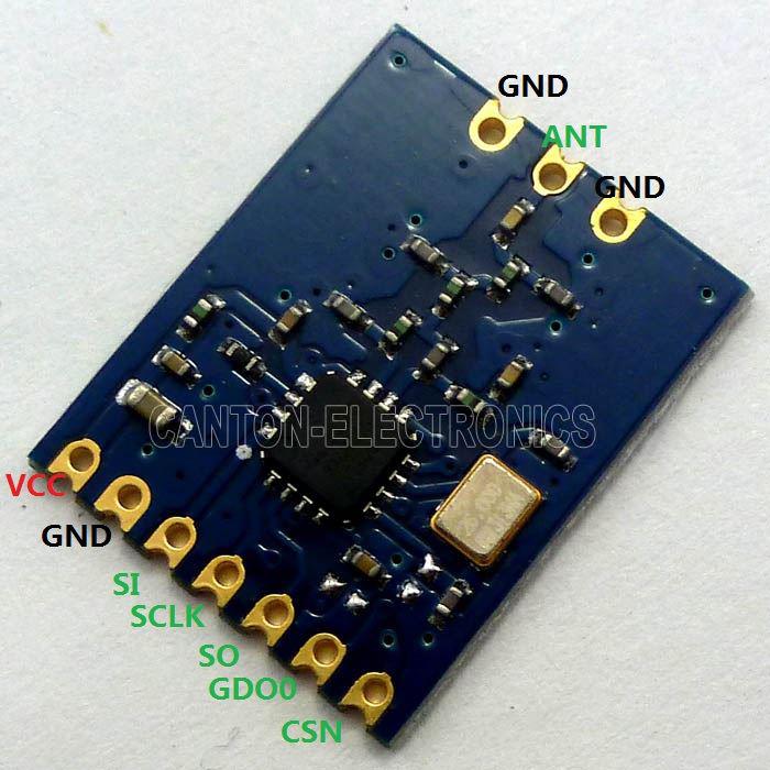
The first big step forward, since my last blog post was made because I (finally) received the CC1150 board I ordered on eBay. This is almost a drop-in replacement for the CC1101 board I blew up by applying to much voltage to it’s pins, and is actually the same chipset as the Itho remote uses. So the traces I recorded using the logical analyzer should be replay-able bit-by-bit.
First I connected the board to my Arduino Pro Mini (clone) running at 3.3 volt (I’m not taking any changes with this board). Then I modified (slimmed down) the code I used during my previous test, so I could just read some default values from the CC1150-registers. I used the Arduino SPI library (not my own bit-banging code) and it worked the first time around! I could read the PARTNUM (default value 2), VERSION (default value 4) and FREQuency (default values 0x1E 0xC4 0xEC). Hurray! Now we are getting somewhere. (my code is on my GitHub repository, in the ReadRegisters example for the Itho-library I’m creating)
The next logical step was to set all recorded registers and sent the parallel data to see if the Ihto would change it’s speed. Adding the code to set the registers was easy, but the code that sends the parallel data proved to be more difficult. This code has to listen to a clock signal that the CC1150 is generating, and on each rising edge of that signal another pin should be set high or low to clock out the (parallel) data. This sounds pretty easy, but is actually harder than I expected, especially when you have to do it at pretty high speeds and with precision timing. I ended up writing 4 versions of the same code, where only one actually worked.
Version 1 used an Arduino library named PinchangeInt to listen to the falling edge of the clock-signal (on the Miso-pin) and then set the GDO1-pin in the right state. This version of the code is the cleanest solution and leaves the reading of the clock-signal to the hardware interrupt handler of the Arduino (actually the ATMEGA chip to be more precise). The problem with this code was that the Interrupt Service Routine was called again, before the previous call had finished setting the GDO1-pin. In the logical analyzer I could see that this resulted in incorrect data being transmitted to the CC1150 and thus to the Itho ventilation box.
void ISR_MISO() {
  // check if there is any more data to send
  if (dataIndexBits < dataLengthBits) {

    byte bufferValue = dataBuffer[bufferIndex];

    if (bufferValue & mask) {
      digitalWrite(GDO0, HIGH);
    }
    else {
      digitalWrite(GDO0, LOW);
    }

    // bitmask trick came from: http://arduino.cc/en/Tutorial/BitMask
    mask >>= 1;

    if (mask == 0)
    {
      mask = 10000000; //reset mask
      bufferIndex++; //goto next byte in the data-array
    }

    dataIndexBits++; //increase bits send
  }
}

void enableMisoInterrupt() {
  pinMode(GDO0, OUTPUT); // sets the digital pin as output

  //queue the first bit, because the code below waits
  //for the first RISING edge to queue the next
  ISR_MISO();

  PCintPort::attachInterrupt(SPI_MISO, &ISR_MISO, FALLING);
}
Version 2 of the code did not rely on hardware interrupts but instead tried to clock out the signal at the exact time the CC1150 was expecting it (this is called Asynchronous transparent mode in the CC1150 datasheet). This meant that I would have to clock out data at exactly 38.46kHz, or one bit every 26 microseconds. For this the Arduino/ATMEGA has a feature called a timer. This is a hardware feature that you can configure to generate a signal every specified time. I used the clean Arduino library TimerOne from Paul Stoffregen to configure the timer. The timer fired, but not at the speed I configured, the fastest time it fired was every 90 microseconds. I think this isn’t a problem with the library but rather a limitation of the Arduino Pro Mini (running at 8 MHz) and not processing the timer-interrupts fast enough.
void enableMisoInterrupt() {
  pinMode(GDO0, OUTPUT); // sets the digital pin as output

  timerOne.initialize(26); //26 us = 38.46 kHz
  timerOne.attachInterrupt(ISR_MISO);
}
Version 3 of the code used the Synchronous Serial Operation mode of the CC1150 (just like version 1) but instead of using an interrupt to listen to the clock-signal I used an endless loop to read the value of the clock. This way I can detect the clock signal switching from low to high, which means the rising edge has taken place. After each rising edge (at which the CC1150 reads the data), I could change the output pin to the next value and wait for the next rising edge to pass. With this code I came a lot closer to the maximum of 26 microseconds that I had, but still not close enough (it was still over 50 microseconds).
void enableMisoInterrupt() {
  pinMode(GDO0, OUTPUT); // sets the digital pin as output

  generateFakeInterrupts();
}

void generateFakeInterrupts() {
  int previousMiso = -1;
  int currentMiso = -1;

  noInterrupts();

  //queue the first bit, because the code below waits
  //for the first RISING edge to queue the next
  ISR_MISO();

  do
  {
    currentMiso = digitalRead(SPI_MISO);

    if (currentMiso != previousMiso)
    {
      //wait for Miso to be high, then the RISING edge has taken place
      //and we can clock in new data
      if (currentMiso == HIGH)
      {
        ISR_MISO();
      }
      previousMiso = currentMiso;
    }
  }
  while(dataIndexBits < dataLengthBits);

  // wait for the last clock to become high
  // so the last queued bit is also sent
  while(digitalRead(SPI_MISO) == LOW);

  interrupts();
}
In version 4 the only thing I changed where the calls for digitalRead and digitalWrite. I switch them for calls to digitalReadFast and digitalWriteFast in the DigitalWriteFast-library. This sped up the code considerably, and I was actually able to respond within the required 26 microseconds.
void generateFakeInterrupts() {
  int previousMiso = -1;
  int currentMiso = -1;

  noInterrupts();

  //queue the first bit, because the code below waits
  //for the first RISING edge to queue the next
  ISR_MISO();

  do
  {
    currentMiso = digitalReadFast2(SPI_MISO);

    if (currentMiso != previousMiso)
    {
      //wait for Miso to be high, then the RISING edge has taken place
      //and we can clock in new data
      if (currentMiso == HIGH)
      {
        ISR_MISO();
      }
      previousMiso = currentMiso;
    }
  }
  while(dataIndexBits < dataLengthBits);

  // wait for the last clock to become high
  // so the last queued bit is also sent
  while(digitalReadFast2(SPI_MISO) == LOW);

  interrupts();
}
Using version 4 of the code (and some extra tweaks here and there), the logical analyzer finally showed the exact same commands being send to the CC1150 as I recorded previously from the remote control. But still the Itho ventilation box did not change it’s speed… While I was looking at my code I left the Arduino running and transmitting a full-button-press every 5 seconds. After about 15 minutes all of the sudden I could hear the Itho ventilation box changing to full speed! Hurray! I must be on the right track, the code does actually do something, only transmitting the same signal over 300 times (20 times a minute for 15 minutes) to change the speed once isn’t exactly ‘working as expected’.
I started analyzing my previous recorded traces again and spotted a few bits that differ between trace v1 and trace v2 of the same button press (full speed). So this is the challenge I’m currently facing. I hooked up the logical analyzer to the remote control again and have recorded 8 new traces of the same button press (full speed). This shows that for the first serial transmission (part 1) only the last 2 bytes change of the 20 bytes sent (see Excel compare sheet).
| v1 | v2 |
|---|---|
| 170 | 170 |
| 170 | 170 |
| 170 | 170 |
| 173 | 173 |
| 51 | 51 |
| 83 | 83 |
| 74 | 74 |
| 203 | 203 |
| 76 | 76 |
| 205 | 205 |
| 84 | 84 |
| 213 | 213 |
| 85 | 85 |
| 51 | 51 |
| 82 | 82 |
| 180 | 180 |
| 170 | 170 |
| 171 | 171 |
| 85 | 77 |
| 75 | 77 |
And for the second serial transmission (still the same button press), a total of 5 bytes change (of the 50 bytes sent):
| v1 | v2 |
|---|---|
| 170 | 170 |
| 170 | 170 |
| 170 | 170 |
| 170 | 170 |
| 170 | 170 |
| 170 | 170 |
| 170 | 170 |
| 171 | 171 |
| 254 | 254 |
| 0 | 0 |
| 179 | 179 |
| 42 | 42 |
| 171 | 171 |
| 42 | 42 |
| 149 | 149 |
| 154 | 154 |
| 102 | 102 |
| 89 | 89 |
| 154 | 154 |
| 165 | 165 |
| 169 | 169 |
| 169 | 169 |
| 154 | 154 |
| 86 | 86 |
| 149 | 89 |
| 165 | 169 |
| 166 | 102 |
| 89 | 89 |
| 150 | 150 |
| 170 | 170 |
| 165 | 165 |
| 101 | 101 |
| 90 | 90 |
| 150 | 150 |
| 85 | 85 |
| 149 | 149 |
| 101 | 101 |
| 89 | 89 |
| 102 | 102 |
| 85 | 85 |
| 150 | 150 |
| 106 | 105 |
| 170 | 170 |
| 106 | 150 |
| 172 | 172 |
| 170 | 170 |
| 170 | 170 |
| 170 | 170 |
| 170 | 170 |
| 170 | 170 |
My first thought went out to a checksum, but the other bytes aren’t changing, so a checksum should not change either. Since the CC1150 is only a transmitter it can’t be responding to messages from the ventilation box. The only possibility that I see is that the remote stores a follow-up number in it’s EEPROM and increments this. I would have expected the numbers to change every button press, but this is where it starts to get weird. The first 8 button presses I recorded (v5 - v12) contain the same values, but the last 2 buttons presses show a different number (for part 1). It isn’t a simple 1 or 10 increment, so what logic is the remote using for these bytes?
| v5 | v6 | v7 | v8 | v9 | v10 | v11 | v12 | v13 | v14 |
|---|---|---|---|---|---|---|---|---|---|
| 170 | 170 | 170 | 170 | 170 | 170 | 170 | 170 | 170 | 170 |
| 170 | 170 | 170 | 170 | 170 | 170 | 170 | 170 | 170 | 170 |
| 170 | 170 | 170 | 170 | 170 | 170 | 170 | 170 | 170 | 170 |
| 173 | 173 | 173 | 173 | 173 | 173 | 173 | 173 | 173 | 173 |
| 51 | 51 | 51 | 51 | 51 | 51 | 51 | 51 | 51 | 51 |
| 83 | 83 | 83 | 83 | 83 | 83 | 83 | 83 | 83 | 83 |
| 74 | 74 | 74 | 74 | 74 | 74 | 74 | 74 | 74 | 74 |
| 203 | 203 | 203 | 203 | 203 | 203 | 203 | 203 | 203 | 203 |
| 76 | 76 | 76 | 76 | 76 | 76 | 76 | 76 | 76 | 76 |
| 205 | 205 | 205 | 205 | 205 | 205 | 205 | 205 | 205 | 205 |
| 84 | 84 | 84 | 84 | 84 | 84 | 84 | 84 | 84 | 84 |
| 213 | 213 | 213 | 213 | 213 | 213 | 213 | 213 | 213 | 213 |
| 85 | 85 | 85 | 85 | 85 | 85 | 85 | 85 | 85 | 85 |
| 51 | 51 | 51 | 51 | 51 | 51 | 51 | 75 | 75 | 51 |
| 82 | 82 | 82 | 82 | 82 | 82 | 82 | 76 | 76 | 82 |
| 180 | 180 | 180 | 180 | 180 | 180 | 180 | 180 | 180 | 180 |
| 170 | 170 | 170 | 170 | 170 | 170 | 170 | 170 | 170 | 170 |
| 171 | 171 | 171 | 171 | 171 | 171 | 171 | 171 | 171 | 171 |
| 85 | 85 | 85 | 85 | 85 | 85 | 85 | 85 | 85 | 85 |
| 53 | 53 | 53 | 53 | 53 | 53 | 53 | 53 | 75 | 75 |
I am going to analyze a bigger set of traces that I recorded for the same button press (full speed). Maybe with more data I can see the logic behind the few bytes that are changing.
Lessons learned:
- Interrupts can come too fast for a library/microcontroller to handle
- Direct port bit changes are faster than using Arduino’s DigitalWrite function
- Exact timing (microsecond precision) is hard (if not impossible on a Arduino)
- Serial communication is nice for debugging, but can screw up your timing when added in the wrong places
- Chinese probes aren’t that bendable (wire broke off at solder joint; fixed with my soldering iron)
- Cleaning up 4 versions of code (for commiting to GitHub) takes more time than creating them!
Other posts in this serie: Part 1, Part 2, Part 3, Part 4, Part 6
3 replies on “Reverse engineering remote Itho CVE ECO RFT – Part 5”
The code library that comes with the Arduino (platform) is very safe and easy to use. The price you pay is speed. It kills it. These APIs are meant for rapid prototyping and for lowering the learning curve. Once you have a clear understanding of what you need to do (I think you do already) you could consider moving to AVR-Studio 6 (free) or writing it in assembly (never done that myself). These options will give you better performance and more control (and more things to manage).
I wonder what happens when you use version 1 of your code (interrupts) with the fast write functions…?
Quite late to the party, but FYI: your version 1 code –> mask = 10000000; //reset mask
This will never work… You’re missing a ‘binary’ indicator, so you’re setting your mask to 10000000 DECIMAL, not binary. So you’re masking with 11110100001001000000b instead of 10000000b :)
Wow! Thanks for replying Vincent! I really didn’t notice this rather big mistake. I would really love to edit and run the first fixed version of the code again and see if it works. But I am currently in the process of moving to another house, so all my electronics have already been stored in boxes. Most likely it will take me at least 2 months to unpack everything and get settled, so this will have to wait. If you do use the code and get the first version working, please do share your experiences in the comments.
In the mean time I will update this blog with your correction and also change the code on GitHub. Thanks for the sharp look at my code!
Your reply