
Reading back my previous blogpost I noticed that it has been a month since my last post! This doesn’t mean the project has stopped or that I’ve lost interest, it just means there is a lot happening in my life and it’s hard for me to find some spare time to do the work needed to advance this project.
I ended my previous post (part 3) with “let’s write some code”. What it should have read was “let’s connect the CC1101 to my Arduino”. This sound relatively easy, but it’s a step I really underestimated.
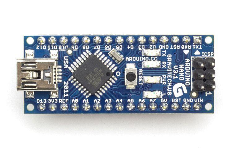
The plan was to connect a CC1101 board I had bought on eBay and connect it to an Arduino Nano (also bought on eBay). I choose the Arduino Nano because it has an USB-connector on the board and that makes it easier to connect it to my pc and to my future IoT-hub (more on that in future posts).
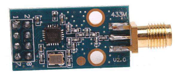
The CC1101 board I ordered has 8 pins:
- GND
- VCC
- GDO0
- CSN
- SCK
- MOSI
- MISO/GDO1
- GDO2
The datasheet on eBay said the board supports a VCC voltage ranging from 1.8 to 3.6VDC. Since the Arduino Nano has a 3V3 output that connection was a no-brainer. The GND is also directly available on the Arduino Nano, no problem. Next were the SPI pins: CSN, SCK, MOSI and MISO. Turns out the Nano has dedicated pins for SPI: SS (CSN) on pin 10, SCK on pin 13, MOSI on pin 11, MISO on pin 12. Sounds simple, right? The only pins that are left to connect are GDO0 and GDO2. I choose pin 2 and pin 9, because that’s what the panStamp library seems to be using, and it’s almost the same combination I’m using (Arduino 328p with CC1101).
This is when I made my first and most crucial mistake, I got so excited that I found the panStamp library and that I had decoded enough data in my previous blogposts, that I had to try out the panStamp code. In my enthusiasm I forgot to double check everything and went ahead and turned on the Arduino Nano (connected to the CC1101) and programmed the code. After a few tweaks, the code that I wrote using the library ran, but I didn’t see the values I was expecting on my logical analyzer. That was the point where I should have realized there was something wrong, but instead I assumed that I had made a mistake in the code and started debugging. I first made the code smaller (fewer statements) so that I could focus on a few commands between the Arduino Nano and the CC1101. Every command send to the CC1101 should be acknowledged by the CC1101 and there are also commands to read back register settings from the CC1101. I thought that I would start by reading back the default values from the registers of the CC1101 after a hard reset, because then I could verify that my code was working. No matter what I tried the CC1101 didn’t return the values I was expecting. So I started using other libraries (the RFbee library is very nice and very well documented). When this library also failed to read the values I was expecting, I created a SPI library (set of methods) from scratch, even skipping the SPI functions the standard Arduino library provides. I bit-banged out the appropriate commands and still the CC1101 refused to return the defaults values.
I think at this point I had spent about 5 evenings & nights writing code and switching between different Arduino’s, when I started suspecting the CC1101 was the problem. I opened up the datasheet for the CC1101 and started reading it from the top. When I got to chapter 1 “Absolute Maximum Ratings” (page 8 of the PDF) I noticed something: “Voltage on any digital pin” “max” “3.9”. I know that I have connected the VCC of the CC1101 to the 3.3v connection of the Arduino, but how much voltage do the other pins of the Arduino Nano supply? From the Arduino website: “Each of the 14 digital pins on the Nano can be used as an input or output, using pinMode(), digitalWrite(), and digitalRead() functions. They operate at 5 volts.” Ouch! That means I have blown my CC1101 on the first power-up and just spend 5 evenings & nights searching for a bug in the code that wasn’t there.
There was nothing more I could do at this moment, but order another CC1101 chipset on eBay and wait. The next day I told this story to a colleague of mine and he pointed out another mistake I made. I bought a CC1101 board, but did not check what the other components on the board did. Turns out the components used on the board made an passive filter between the antenna and the CC1101, limiting/optimizing the signal to a frequency off 433MHz. Since I need 868 MHz, this board (and the one I just ordered) would probably have never worked on the Itho ventilation box.
I started searching for another CC1101 of CC1150 board which does support 868MHz. This is very hard/impossible to find on eBay. All manufacturers seem to optimize their boards for 433MHz. My colleague suggested I try out the Hope RF69 chips. These are very popular chips, since Moteino and JeeLabs both are using this (and similar chips). So I ordered a few (4) chips from a Dutch supplier and I am now waiting for the 2mm pin headers from China to solder wires to these chips.
Lessons learned from all this:
- Read the datasheet before you connect anything! Not all chips can handle more than 3.3V on their input.
- Carefully select the RF transmitter you need. Each board is usually optimized for a specific frequency.
- Not all RF transmitters use the same commands/registers, not even the ones from the same manufacturer. Again, read the datasheet!
- Order at least 1 component more than you need, so you can check/swap them if one is broken/blown.
Ps. Several people have asked me to share the traces from the logical analyzer I captured. I have put all files on my GitHub repository.
The *.logicdata files can be opened with the free Salaea Logic software. The *.csv files contain extracts of the *.logicdata files. The *.xlsx files combine all extracts and add references to the datasheet. Not all commands contain xlsx-files yet, I’m currently focusing on the ‘full’-command. Please let me know if you find these files usefull and/or want to automate the Itho yourself!
Other posts in this serie: part 1, part 2, part 3, part 5, Part 6
1 replies on “Reverse engineering remote Itho CVE ECO RFT – Part 4”
Yes, indeed it all starts with the datasheet. I have a dark molten patch on one of my breadboards to remind me. There is also a trap in buying doubles, if it does work in one go you are left with spare parts you will probably not use again. Anyway I think you are doing great.
Your reply