
Now that I have saved the data from the logical analyzer, it’s time to do the actually analysis. The analyzer software helped me interpret the SPI protocol into hexadecimal values (so I didn’t have to count each bit individually). But still there is a lot of communication between the ATMEL microprocessor and the CC1150 chip to changes the speed of the Itho ventilationbox.
The first thing I noticed was that when you press a button once, 3 identical messages are transmitted using the CC1150. From what I’ve read this is very common in RF-communication, this way you have a higher change that at least one message will arrive at the other end. The transmission of one message takes about 45 milliseconds then the remote waits 55 miliseconds to send the next message. In total the remote is out of sleep mode for a maximum of 245 milliseconds after 1 button is pressed.
Each message consist of 5 things:
- SPI communication to initialize the CC1150
- serial communication to sent the first part of the message
- SPI communication to reset and re-initialize the CC1150 for the second time
- serial communication to sent the second part of the message
- SPI communication to turn off the CC1150
These 5 steps are repeated identically 3 times for each button you press on the remote. According to the datasheet, the CC1150 would have been able to sent data without using the serial communication mode, it would even perform better if they used this method (since the CC1150 can take care of all the timing aspects). But Itho choose to use the old serial communication method, probably for making the protocol backwards-compatible with older Itho ventilationboxes that do not have a CC1150 yet.
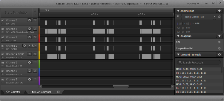
I started reverse engineering the SPI communication first. For this the CC1150 datasheet and the blogs from @cybergibbons where invaluable. To make things a little bit easier for myself, I created an spreadsheet with the captured data on one tab and several lookup tables for Command Strobes and Config Registers from the datasheet on the next. This way I could easily translate the bytes being sent. The first part of the sheets looks like this:
| Time [s] | Packet ID | MOSI | Strobe | Register | MOSI meaning | Register/ Command/ Value | Value meaning |
|---|---|---|---|---|---|---|---|
| 0.000257875 | 0 | 0x30 | x | Reset chip | SRES | ||
| 0.000425875 | 1 | 0x02 | x | GDO0 output pin configuration | IOCFG0 | ||
| 0.000441875 | 1 | 0x2E | 0x2E | 0x2E | High impedance (3-state). | ||
| 0.000516125 | 2 | 0x0D | x | Frequency control word, high byte | FREQ2 | ||
| 0.000532250 | 2 | 0x21 | 0x21 | 0x21 | |||
| 0.000606500 | 3 | 0x0E | x | Frequency control word, middle byte | FREQ1 | ||
| 0.000622500 | 3 | 0x65 | 0x65 | 0x65 | |||
| 0.000696750 | 4 | 0x0F | x | Frequency control word, low byte | FREQ0 | ||
| 0.000712750 | 4 | 0x6A | 0x6A | 0x6A | 868,299865 MHz |
The first 3 columns (Time, Packet ID and MOSI) came from the logical analyzer. The 2 columns after that (Strobe Register) I’ve added myself. These 2 columns indicate which lookup table the next two columns (MOSI meaning, Register/Command/Value) should use to lookup the meaning of the MOSI value. The last column I’ve added manually to translate the values of each register/command to readable text.
Let’s look at 3 examples. The first packet ID 0 sents MOSI hexadecimal value 0x30 to the CC1150. In the datasheet on page 42 in table 25 this value translates to Strobe Name “SRES” with the description “Reset chip”. This sounds pretty normal; start by resetting the configuration to the default values before configuring anything else (remember the chips comes out of sleep mode after each button press).
The second packet has ID 1. It consists of 2 bytes. The first byte has hexadecimal value 0x02. The second byte has value 0x2E. Looking up up the first byte (0x02) in the datasheet, on page 43 table 26, shows that this is a register address called IOCFG0. The second byte (0x2E) is the value written to it. Looking at page 45 shows that this register consists of one byte and the 8 bits in this byte configure 3 seperate fields:
| Bit | Field Name | Reset | R/W | Description |
|---|---|---|---|---|
| 7 | GDO_DS | 0 | R/W | Set high (1) or low (0) output drive strength on the GDO pins. |
| 6 | GDO1_INV | 0 | R/W | Invert output, i.e. select active low (1) / high (0). |
| 5:0 | GDO1_CFG[5:0] | 46 (0x2E) | R/W | Default is tri-state (See Table 24 on page 38). |
If we translate hexadecimal value 0x2E to binary (bits), it becomes 00101110. Looking at the table above GDO_DS has bit 7 (the most significant bit, the first bit on the left) which has value 0, so GDO_DS is low. GDO1_INV has bit 6 (the second bit from the left) which is also 0, so GDO1_INV is high. The 6 other bits (101110) are the value for GDO1_CFG. To know what they do, we need to lookup table 24 on page 38 in the datasheet. There it says that 0x2E (the hexidecimal value for binary 101110) is “High impedance (3-state)”. In short this means the GDO1 pin outputs data depending on the state the CC1150 is in (either a SPI signal output, or a clock signal, or a temperature value).
UPDATE: Two very observant people noticed a flaw in my calculation below. So I’ve striked out and corrected the errors, which have a significant effect on the frequency.
The next 3 packets sent to the CC1150 configure registers FREQ2, FREQ1 and FREQ0. In the datasheet on page 47 it says we can calculate the value of FREQ using these three register values. All we have to do is paste the values of the 3 registers after each other: 0x21 0x65 0x5A 0x6A. In binary notation this would be 00100001 01100101 01011010 01101010. Using a calculator we can translate this long binary number to a decimal: 2188634 2188650.
Now that we have FREQ we can calculate the carrier frequency using the formule on page 34 in the datasheet:
F_CARRIERFREQ = FXOSC / 2 ^ 16 * (FREQ + CHAN * ((256 + CHANSPC_M) * 2 ^ (CHANSPC_E - 2)))
We know that the remote uses an oscillator running at 26MHz from the photo in my earlier blog. So FXOSC is 26000000 (Hz). The values for the other registers used in this formule appear further down the captured data (which I haven’t shown in the first table to keep this blog post ‘short’). The values are: CHANSPC_M = 248, CHANSPC_E = 2 and CHAN = 0. If we fill these values into the formula we get:
F_CARRIERFREQ =26000000 / 2 ^ 16 * (<del>2188634</del> 2188650+ 0 * ((256 + 248) * 2 ^ (2-2)))
F_CARRIERFREQ =26000000 / 65536 * 2188634 2188650
F_CARRIERFREQ = 866699064 868299865 Hz
F_CARRIERFREQ = 866,699064 868,299865 MHz
Looking at all the data before the first serial transmission, we see the following SPI strobe commands/registers set:
-
SRES - Reset the chip
-
IOCFG0 = GDO0 is configured as input (for serial TX data).
-
IOCFG1 = Serial Clock. Synchronous to the data in synchronous serial mode. In TX mode, data is sampled by CC1150 on the rising edge of the serial clock when GDOx_INV=0.
-
FREQ2, FREQ1, FREQ0 = 868,299865 MHz
-
MDMCFG4, MDMCFG3 = 4004,47845458984375 baud
-
MDMCFG2, MDMCFG1, MDMCFG0
- MOD_FORMAT = 2-FSK
- MANCHESTER_EN = Disable
- SYNC_MODE = No preamble/sync word
-
CHANNR = 0
-
DEVIATN = 25,390625 KHz
-
FREND0
- LODIV_BUF_CURRENT_TX = 2
- PA_POWER = 7
-
MCSM0
- FS_AUTOCAL = Automatically calibrate when going from TX back to IDLE
- PO_TIMEOUT = 64
-
FSCAL3, FSCAL2, FSCAL1 = all default values
-
FSTEST, TEST2, TEST1, TEST0 = all values given by SmartRF studio according to the datasheet
-
PKTCTRL0
- WHITE_DATA = off
- PKT_FORMAT = Serial Synchronous mode, data in on GDO0
- CRC_EN = disabled
- LENGTH_CONFIG = Infinite packet length packets
-
ADDR = Broadcast
-
PKTLEN = 255
-
SNOP = Burst write PATABLE
-
STX = Enable TX. Perform calibration first if MCSM0.FS_AUTOCAL=1
I have removed the duplicate strobe commands and registers being set. Hopefully when I write my own code I don’t have to set the same register multiple times to configure the CC1150 correctly. In the datasheet I didn’t find any reference that setting the same register multiple times would be necessary, so the logged data I observed could simply be a programming error made by Itho, or it is necessary for the CC1150 and isn’t specified in the datasheet.
The next step is to decode the recorded serial data:
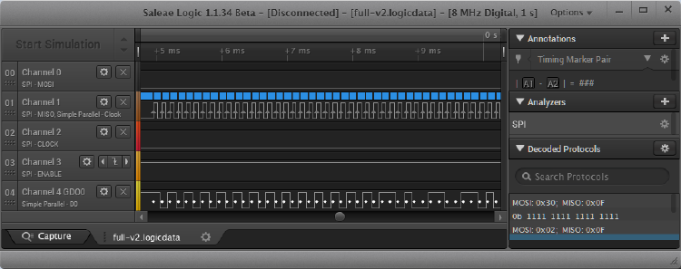
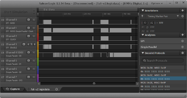
This is a bit more fuzzy-logic than the SPI data, since it isn’t specified in the datasheet for CC1150 and is specific for the Itho ventilationbox. From the registers set with SPI I have gathered that the data will be sent over GDO0 (channel 4 in the picture) and that this data needs to be transmitted on the rising edge of the clock signal provided by the CC1150 on the SO (channel 1 in the picture). Luckily the logical analyzer can be configured to decode the same channel using 2 different protocols (SPI and Simple Parrallel). Exporting this parallel data results in:
| Time [s] | binary value | Last bit | Byte value |
|---|---|---|---|
| 0.004950750000000 | 0b 1111 1111 1111 1111 | 1 | |
| 0.005075625000000 | 0b 1111 1111 1111 1110 | 0 | |
| 0.005200500000000 | 0b 1111 1111 1111 1111 | 1 | |
| 0.005325375000000 | 0b 1111 1111 1111 1110 | 0 | |
| 0.005450250000000 | 0b 1111 1111 1111 1111 | 1 | |
| 0.005575125000000 | 0b 1111 1111 1111 1110 | 0 | |
| 0.005700000000000 | 0b 1111 1111 1111 1111 | 1 | |
| 0.005824875000000 | 0b 1111 1111 1111 1110 | 0 | 10101010 |
Only the last bit of the second column is relevant data (it actually changes), so I’ve added the third column to show only that bit. I’m assuming the data is being sent using one byte at a time, so after every 8 bits I calculate the binary value of the byte and show this in the fourth column.
The first serial transmission contains exactly 160 bit values, which translates to 20 byte values. For the second serial transmission I’m still a bit uncertain how many byte values are sent. I’ve recorded multiple traces for the same button press and the number of bits varies between 404 and 408. Most likely my logical analyzer isn’t fast enough to record all bits being sent and that is why the total number of recorded bits varies. For the moment I’m going to assume 408 is the correct value, since this means there are 51 bytes being sent. I will have to look at the recorded traces of the other buttons to determine the exact number or else simply try to write some code and see when the ventilationbox actually changes speed. Let’s write some code for the Itho ventilationbox and the CC1150 chip next!
**Other posts in this serie: **Part 1, Part 2, Part 4, part 5, Part 6
15 replies on “Reverse engineering remote Itho CVE ECO RFT – Part 3”
Hi Rogier, good progress! I also have an Itho box and which i would like to couple to my rfxcom. Thanks for the good worrk.
Hi Gerben, I have no experience yet with a rfxcom. But if it can sent an rf signal on a specific channel with a specific modulation than it should be possible to sent the same signals as the Itho remote. When I have a working example with a CC1150 or CC1101 chipset, I might also look at sending the signal with a simpeler rf-chipset and/or a rfxcom. Keep on reading my blog for further updates!
Regards, Rogier.
Hi Rogier,
Nice job! I have the same wish, but not the same skills:-) You lost me in this third part, lol. But form what I understand, you’ll be able to write some code now, so that the Itho can be controlled? Great! Would that be a generic code? Or is there some kind of ID that makes each box unique and a generic code would not work?
Anyhow, keep up the good work. I can’t wait.
Hi Pieter,
I must admit this last post was very in-depth. This is all very new to me as well, but I’m trying to document my steps as good as possible. I’ve got a background in software enginering, but not in electrical enginering nor in embedded software, so bare with me. :-)
But your summary is right, I’ll be able to write some code now that controls the Itho. I’m currently busy writing the code, when that’s finished I’ll write a follow-up post about it.
As far as I can tell, only the remote controls have a unique id. When you first power-up the ventilation box you have a short time (i think about a minute) to register all remote-controls in the house with the box. You do this by pressing two buttons on the remote at the same time. The remote then sents out a signal with it’s id and from that point on that remote is able to control the ventilationbox. The messages that I’ve recorded contain the unique id for my own remote. This id can be registered with any Itho ventilationbox, so my code should work on all boxes.
It would be even better if I had a second remote to test with, because then I could determine which bytes of the protocol contain the id. When I’ve seen that the code works, I’ll be asking around for another remote control that I can borrow to see if I can give each home-automation-controller a unique id.
Thanks for your reply! (it’s motivating to hear that other people would like to use the same code)
Thanks, that makes sense. I’ll be patience!
Hi Rogier,
Very nice job indeed. I am also tinkering with a Software Defined Radio and an ITHO RF transmitter. No background in software or electrical engineering whatsoever. :/ My goal is to make an Arduino receiver because I have an old Itho WTW ventilation system which is not compatible with a RFT receiver. I see I’ve got a slightly different (programmed) ITHO transmitter, the SDR receives a signal at about 868,240000 MHz, also the number printed at top the PCB in ‘7 segment display’ font is “1033” instead of “1413”.
It’s the 536-0125 RFT transmitter unit: http://www.ithodaalderop.nl/sites/default/files/documents/historisch_overzicht_rf_bedieningen_ventilatie_units.pdf
Soldering probe wires onto the PCB isn’t going to do it I see. I think I’ll buy some extra 3rd hands and use my Bus Pirate / Logic Sniffer combo to read the SPI traffic.
Can you share the spreadsheet with all the captured data for study?
With regards,
Sijmen
Hi Sijmen,
Nice to hear that you would also like to control the ITHO box!
The frequency you’ve found is just about correct. I see that I’ve made a mistake writing my blog above. If you look at the first table in this blogpost, on the last line you can see the frequency I’ve calculated originally based on the SPI data: 868,299865 MHz. Further down in this post I tried to reproduce the formula I used to calculate it and made a mistake which resulted in 866,699064 MHz. So your 868,240000 MHz is very close to my correct calculation. (I will correct my blogpost as soon as possible)
In my first blogpost about reverse engineering the Itho remote I’ve included a link to a blogpost from a collegue of mine, which also has the older ITHO remote: http://zigbeeme.blogspot.nl/2014/10/decoding-itho-rf-protocol.html He has also included some Arduino code that works on his ITHO box. So maybe, with some adjustments, it could work for you as well.
I’m busy writing a follow-up post on my progress and will link to the captured data in that post.
If you make any progress with controlling your ITHO-box, please let me know, I would love to hear/read about problems you ran into and how you solved them.
Keep on reading this blog for my progress!
Hi Rogier,
I don’t know if you are still working on reverse engineering the RF messages?
Two days ago I started reverse engineering the RF messages myself. I am a software engineer (PC) and played with microcontrollers a few years ago (control stepper motor and some leds only). I have knowledge of reverse engineering in the PC field, but not on the electrical level.
The reason I started working on this is because Itho doesn’t have any way to control the ventilation based on humidity. Ofcourse there are easy workaround solutions by using controlling the perilex or accessing the RF remote buttons but I don’t like those solutions. Also it will be a fun project for me because I am new into this field.
I shortly investigated the possibility of extracting the firmware out of the AtMega. Probably the microcontroller is protected so I skipped this possibility.
So last week I ordered a crappy logic analyser on ebay. It is giving me some noise in the analyzer software from time to time. But it was only 23 euro’s including shipment cost.
I almost have a clear picture of the whole messages which are being transferred. Data fields inside the messages consists of:
I’ve made a small .net program which I use to predict how the next message will look like. It works nicely and matches the results from the analyser.
One of the 6 fields with sequence data is not completely clear to me. It depends on the selected mode but even after 1000 messages I cannot find a logic in it. My guess is there is no logic in this one and it is used to make reverse engineering more difficult. I know how the field changes based on the selected mode. In the end the number in this field is even or odd. Maybe this is the only requirement on this field (the explanation in the paragraph below supports this). I can only find out by testing with a microcontroller. (I still have to order some parts).
I don’t think there is an unique id for each remote. The longest sequence of bytes used by Itho is 256 bytes long. In combination with all other sequences which are running across the different messages you will get 256 different messages. Initialisation of a new remote control by pressing two buttons for one second is probably needed so the base unit (CVE) knows which message (based on sequence) is expected next. This is just my guess. Your story about the CVE which started to work after 300 messages fits my findings. I guess there were no 300 messages transferred but only 256! The same message is repeated after 256 messages.
Things I have to do:
When I am 100% certain (by testing) about all my findings then I will put them in a document and post them somewhere on a domotica forum.
After two CR2032 batteries which were drained empty after a few hours of analyzing I concluded the remote control stays active when there is a lot of activity on the buttons. Don’t know if this is true. Maybe the logic analyzer itself is playing a role in this. Now I am just removing the battery when I am not analyzing.
If you are interested in the .net application I made then I can send it to you. The source will reveal how the sequences are calculated for the messages and how the next message can be predicted.
Kind regards, Patrick
Hey Patrick,
Thanks for your long and insightful comment! I would love to receive the .NET application you wrote. Can you email it to “Rogier dot Reedijk AT gmail dot com”? Or else create a simple GitHub repository and post a link? I would also love to see a picture of how you connected the analyzer to the remote control. Did you also use helping hands and pins? And if it’s not to much trouble I would love to receive some logical analyzer capture files you made. Because with those I could find out which bytes change between different remote controls!
I’m still working on reverse engineering the messages and took a big step forward this weekend. I’ve got all 4 buttons working now and I’m busy writing a blog post about it (should be up this weekend). The source code is already uploaded to my regular GitHub repository for this project: https://github.com/xs4free/Itho-library And the most recent logical analyzer files (and my own C# program) are in another repository: https://github.com/xs4free/Itho-project
I think that I understand most of the data that’s being transmitted by the remote. It’s a bit much to explain in this comment, so please read my next blog-post that should be up on this blog tomorrow.
My goal is almost the same as yours, I want to control the ventilation based on the humidity in my bathroom. Only, I want to keep the sensor and the ventilation control separated. So I want to create a home-automation server that reads the humidity and based on that value, changes the speed of the ventilation.
I also investigated extracting the firmware from the remote, but came to the same conclusion, the AT Mega is most likely protected. And that would make it nearly impossible.
I’m looking forward to hearing from you! And would love to help where I can. If you buy the same RF board (CC1150) as I have bought, than you can use my code and be up and running very quickly!
Kind regards, RogierR.
I just mailed you all my files including a photo.
I soldered pins on the print so I could easily connect the analyzer. I don’t have helping hands or a lot of tools so this was the only option for me.
I’m also going to use it in my bathroom. Maybe I will connect everything to a base system, it would be nice to be able to make config changes on a touchscreen. I already did some quick research on the OpenTherm protocol because that would be the next step. I want to control humidity by the ventilation system and by controlling the temperature.
I assumed the reverse engineering would be the hardest part so that’s why I started with this. If I didn;t manage to reverse engineer then I didn’t waste much money on this project (except for the programmerdebugger board).
Thanks for the photo and the explanation! Soldering pins to the testpads seems like a very stable way to analyze the messages between the AtMega and the CC1150.
I have also been looking at the OpenTherm protocol and currently have all the parts to create an OpenTherm Gateway: http://otgw.tclcode.com/ That will most likely be my next project after I create a humidity sensor for my bathroom!
I have compared my messages with one of yours and some values are different.
Byte 6,7,8,13,14,15,36,39,40,41,58 (zero based index).
In my messages these bytes always contain the same value. So they seem to be connected to the device itself. Maybe the values are set during initialisation of the remote, maybe they are fixed.
If there really is some unique reference to each remote then I am wondering why the whole circus with changing sequences is used. To lower the chance of interference with other RF transmitting devices? Or only because of reverse engineering? Don’t know if there could be other reasons.
I was also thinking about your message which was accepted after 300 resends. What happens when the base station misses one message from the remote? Will it be out of sync until init of the remote? or are the sequences not that critical and allow some mistakes in it? I was guessing for the last one because otherwise Itho could get a lot of complaints from customers. I just checked this point on my CVE. I unplugged the power and used the remote a couple of times. After putting back the power it still works using the remote. Also a battery change did not introduce any problem. So it allows some missing messages during transfer. It would be interesting to know how many missing messages are accepted.
I’m going the take a closer look at the excelsheet you sent me.
Do keep in mind that the binary data you have recorded comes from 2 different messages, that are transmitted on 2 different frequencies. The first message is exactly 20 bytes long and the second message is 50 bytes plus 3 bits.
I do think each remote has a programmed or generated unique identifier. I don’t know if there is any logic in the bytes for this identifier (maybe it has a checksum of some sorts). Currently I have recorded analyzer traces from 2 different remotes, so I have 2 unique identifiers. If my “join” command works (I need to test this) then everyone should be able to use my code and use the identifier from my remote.
The changes of the sequence number is used by the ventilation box to determine if you have pressed the same button multiple times. This is needed for the timer button, because if you press it once the box will run at full speed for 10 minutes, if you press the timer button twice the box will run for 20 minutes, and so on. If the RF message would not contain a sequence number, the ventilation box would not be able to distinguish between receiving the same message multiple times and receiving a second button press.
Thanks for testing what happens when you press the remote buttons without the box being powered on! I hadn’t gotten around to testing that yet.
I have been testing my code for one evening now and it is working perfectly. In code I’m using the same identifier as the physical remote and both remotes work fine at every button press. So the ventilation box isn’t checking that the sequence numbers are increasing/decreasing. This leads me to believe that my current code is overly complicated (i’m keeping track of my previous buttons press and 2 counters in the Arduino). If I find some time, I’ll experiment some more with the code and see if the code works with a fixed number.
Please read the last blogpost I added today and let me know what you think!
Hi Rogier and Klusjesman,
Great reading your blogs about the investigation on the ITHO system. I have a similar system in my house installed and am very interested in your final results. Were you able to complete it, and control the system by your own remote / domonica?
Thanks. Marco
Hi Marco, If you read my last post, http://www.progz.nl/blog/index.php/2015/05/reverse-engineering-remote-itho-cve-eco-rft-part-6/ , you can read how far I got. I haven’t integrated my controller into a home automation system yet, but I am able to control the Itho ventilation box. Currently I’m very busy packing, because I’m moving to a new home within a few weeks. The new home currently does not have an Itho box, but does need a new ventilation system. So as soon as I am settled in, and have replaced the box by an Itho, then I will try and integrate it into a home automation system. What system are you using? Or what system do you like?
Your reply